


|
back to www.audiodesignguide.com |
To get more information contact me at: webmaster@audiodesignguide.com |
Hi-End Class A-AB Hybrid
Amplifier - the reference
started on November 30 st , 2010
|
|
|
|
|
INTRODUCTION
This amplifier does not born to
be a normal hybrid but to create a my reference better than any other design.
The design of the amplifier stage and of the power supply are inspired to vacuum
tubes amplifiers to follows the same characteristics in the sound but increasing
the capacity to load any loudspeakers without problems.
I have got good result with the my previous
Power
Follower 99 and
Hybrid 2010
but
now I am want a step over and the
first listen on one test channel confirm it.
There is an incredible detail and no
coloration on any frequency band, much
more than any my other design.
In the output stage with the
Circlotron design , the single Mosfet and the CLC power supply for
all stages will help to get the target result.
If I compare this project to others this is a not common design, also my
PF2007 system
is less neutral because need the output capacitor.
The my previous hybrid designs are not very cheap but these need a budget lower
than the necessary to build a serious vacuum tube amplifier like my
300B PSE,
2A3 PSE or
GM70/813.
In this new hybrid project the budget will be not
considered and many time will be lost to search the target point.

UPDATE August 2012:
There is a
prototype of this type of design developed in 1995 and published in 2004 in several editions by Yury Nagorny:CATHODE CAPACITOR
The unique problem of this design is
the cathode capacitor on the first stage because it affect the sound
but I cannot eliminate it.
It can be considered also an advantage because you can use this capacitor to modify
the sound of your total system.
Some candidates for this cathode capacitor are:
1) Sanyo OS-Con - very neutral but a little bit too hard
2) ELNA Cerafine - very smooth, good to
play normal CD
3) ELNA Silmic II - less smooth than Cerafine but still too much
for me
The value of this cathode capacitor
modify the low frequency band so it must be decided only after some measurements
on the specific circuit (see
the differences in another driver circuit).
In my last GM70 SE dc
coupled amplifier with Fiat
transformers I have got a good benefit
using a led ( in the optocoupled) instead of cap/res. on cathode but here I
cannot apply it because the low frequency band will be too much compromised.
INTER STAGE TRANSFORMER
The quality of the interstage transformers is very important in this design and
you cannot use any other type without compromise the final result.
The normal Lundahl
LL1671/20mA is very good but you can ask for the
Amorphous strip
core version used in my
Hi-end
headphone amplifier and in my
DAC End.
 |
The
Spice simulation show an incredible
slew-rate (20V in 200ns) because the mosfet are driven with a tube with a low
internal resistance (near to 2Kohm) and an interstage transformer with a turn
ratio 2:1 reduce it (4 times) this value (2Kohm / 4 = 500ohm) (here
the .cir). MOSFET
In my test
2SK1058 (Hitachi/Renesas)
and
ECX10N20R are much better than BUZ900P
(Magnatec) as
distortion value but the
ECX10N20R (Exicon) are better than
2SK1058 because have the same distortion value but a better damping
factor.
If we increase the power supply to 40
or 45VDC the
ECX10N20R show a limit and for all the best bias point is 1000mA.
In the simulation the output impedance is about
630mohm on all the
frequency range with the mosfet
ECX10N20R and about 1 ohm using the 2SK1058
and
ECX10N20R. |
 |
The my idea for this design is to use only common components easy to find so no custom transformer will necessary and 3 models of tubes will be tested.
This project could be considered ecological if compared to many other my design because with only 180w we have a two channels with an output power about 30w.
VOLTAGE AMPLIFIER
To get a good output distortion decay in any condition I
have decided to use a single tube in this stage.
I have searched a tube with a very good linearity for large swing and low anodic
resistance to drive the output stage without problems.
This tube should have an amplification factor
greater than 40 to connect this amplifier
directly to the CD player or phono pre-ampl.
To get 20w on 8ohm we need:
P=V * I and I = V / R =>
P = V * V / R => V = sqrt (P * R ) = 12.5Vrms
so if we want a sensibility of 0.5Vrms we need
Amplifier factor tube = 12.5 / 0.5 = 25
Using the LL1671/20mA with the turn ratio 4:1:1 => 2:1 we need a amplifier factor
tube of 50.

|
Many of these tubes have a plate resistance about 2Kohm but only the D3A, 6C45 and 5842 have an amplification factor greater than 40. D3A specifications in triode connection:
|
6C45 specifications:
|
5842 specifications in triode
connection:
|
|
CURRENT AMPLIFIER
The most simple design to create a class A current amplifier is the
mosfet.
This design is inspired to the
Circlotron
US Patent n.
4229706 by James W. Bongiorno and to the
Thorens TEM
3200.
POWER SUPPLY
I have design the power supply to
follow a single ended amplifier style but you can use a common solid state
design.
The CLC power supply skip any noise problem and it is superior to any pure
capacitor design also if large value are used.
In the following simulations with PSU Designer II you can see the big difference
in residual noise, with CLC type we get a pure sine wave so it mean low
harmonics.
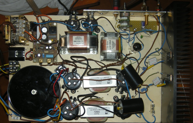
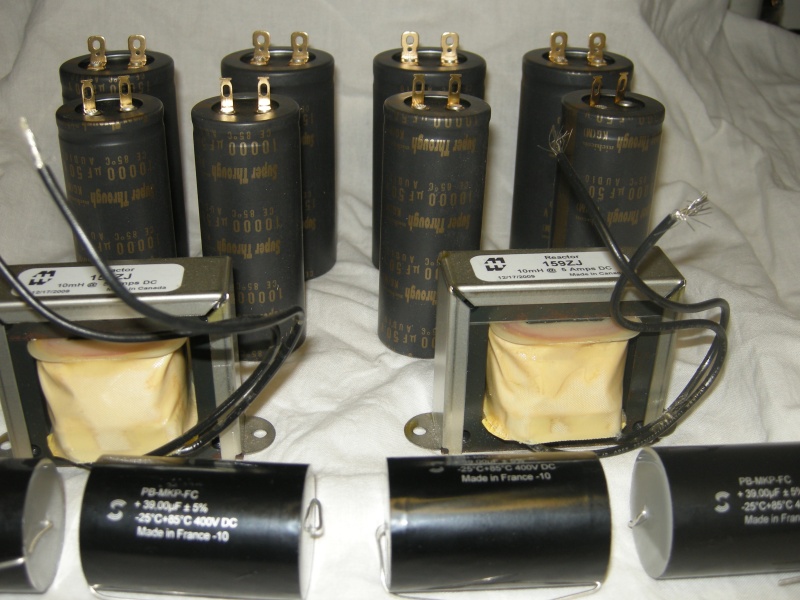
The Hammond 159ZJ (L=10mH Rdc=0.16ohm
Imax=5A) used in this amplifier are not difficult to integrate in any amplifier
because these have a compact size and these are not expensive.

There are many good capacitors to use in audio amplifier power supply but only few of these give hi-end performances:
For this project I have decided to use the Nichicon Super Through on output section and BlackGate (old stock) on vacuum tube stage because both these types will give extreme performances.
To increase the speed of the power supply has been inserted a 39uF Solen MKP in parallel to the electrolitycs.
It is not necessary a DC filament with slow turn-on but it increase the vacuum tube filament and it can be used also for the mosfet gate bias voltage.

LAYOUT
This amplifier need a chassie with heat
sink to dissipate many power also if it is not work in a pure class A operation.
The my choice is the HiFi-2000 mod. Pesante dissipante 5 units with 10mmm
frontal panel got at Audiokit webshop.
On paper each lateral heat sink of this chassie have a capacity of 0.25 °C/W so
it will keep the output devices in a good safe area also when the environment
condition are terrible 35 °C.
Follows a good table to have an idea of the output power and relative heat sink
necessary per each channel.
This layout optimize the signal path and reduce it to few centimeter.
MEASUREMENTS
IMPORTANT: In all these measurements I have set the bias voltage for the minimun distortion, BUZ900P have this point at 30Vdc 900mA, the 2SK1058 at 30Vdc 1600mA and the ECX10N20R at 30Vdc 1550mA.
Environment:
Environment:
Environment:
Environment:
Environment:
Environment:
Environment:
PHOTOS
CONNECTION GUIDE

WINSPICE SIMULATION
To optimize the circuit I have simulate it with Winspice.
PROTECTION
see Amplifier End