
| www.audiodesignguide.com |
After the good result obtain by the Power Follower, the last test on DAC and the Cables test is born the idea to create an integrated system to get the best sound.
The following image show the incredible short signal path obtain in this system.
Since to be incredible but it is true: only 7 components on the signal path:
With this design we have also this characteristics:
No feedback in any stage
All class A operation on any stage
Only 2 amplifier stage (one vacuum tube and one mosfet)
Only one capacitor on the signal path (the output cap.)
No resistors on the signal path if we exclude the stepper attenuator
A single differential voltage amplifier
Perfect balanced to unbalanced signal converter using the interstage tranformer
Max linearity of vacuum tubes because these are loaded by the transformer inductance instead of resistor
Max energy transfert from voltage stage to current stage using the interstage tranformer
No coupling of the signal current from power supply on current amplifier
Constant current flow from the power supply on current amplifier
The power is enough to drive any kind of loudspeakers (also low efficiency, ESL, magnetodinamic)
Power supply in virtual battery operation for voltage and current amplifier
Max protection of loudspeakers
on any condition because there is the output capacitor
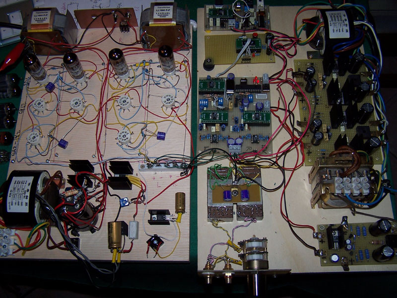
If you want to see the my test environment to check different DAC chips and different vacuum tubes click here.
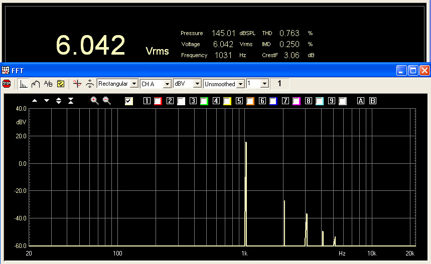
The voltage amplifier and the current amplifier has been simulated with Winspice compatible with Spice3f4.
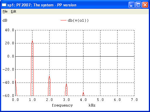
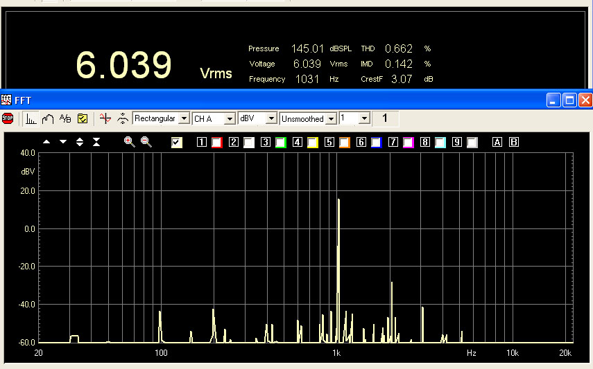
It show a good distortion spectrum with a value about 0.2% at 12Vrms 6ohm load => 25watt (3.7A bias 40V power supply)
DAC STAGE (comp. 1)
For the DAC test result look my webpage "DAC FINAL".
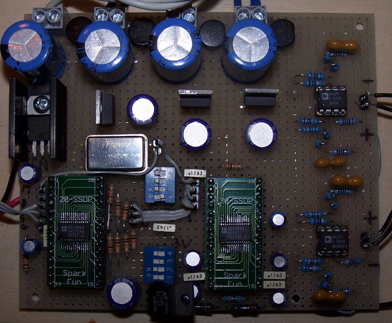
To get the target of only seven components on the signal path is possible to use a DAC chip with integrated I/V converter like the Wolfson/Crystal chips or a Burr-Brown PCM1704 with a passive I/V converter but I like the sound of the AD1955 with an active I/V conv. build using the OP275 so this is my DAC board.
This board include a power supply with 1 x LT1086CT3.3 (AD1896 core), 2 x LT1086CT5 (one for tha digital section and one for the analog section) and 2 x LT1086CT12 (for the I/V stage).
All the capacitors on the power supply and bias are Sanyo OS-CON.
Soon I will create a pcb board for this DAC.
STEPPER ATTENUATOR (comp. 2)
 |
In all my project I
use DACT stepper attenuators instead of normal ALPS and NOBLE
potentiometers because only the DACT are neutral for the signal. For this project has been used a 4ch to work on the balanced signal.
|
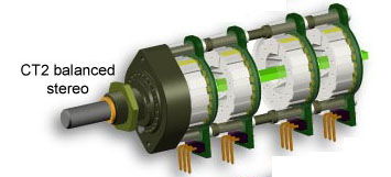
INTERCONNECT CABLE (comp. 3)
 |
Include all these 7 components in a single
chassie was impossible so I have separated the digital section with DAC
chips and DACT stepper attenuator. After my big experience with the cables published on "Cable test" I can assert that the quality of cables is very important. This because I know that many DIY forget it or think to create cable with very cheap materials. My choice is a semi custom cable build using 2 x Q-Audio TAO spare cables with Neutric XLR connectors. This cable have also the propriety of "clear the sound". |
VOLTAGE AMPLIFIER STAGE (comp. 4 & 5)
 |
This stage receive the balanced
signal from the DAC chips and it drive the output mosfet. The resistors on input are not on the signal and these can be eliminated if a passive volume control is used (like a 4ch DACT stepper attenuator). To drive the output mosfet the voltage stage should have low distortion in medium voltage output (15-20Vrms), low output impedance (no more than 1000ohm) and enough gain to be driven directly by the DAC chip (min 17x). The low output impedance is necessary to get a good high frequency cut-off because the mosfet input capacitor is about to 1500-3000 pF. Ft(-3db) = 1 / ( 2 * 3.14 * Rout * Cin) = 1 / ( 2 * 3.14 * 1000 * 3000E-12 ) = 53 KHz |
Follows the table with the characteristics of some tubes valid for this design (for the last 2 columns see below).
| tube | ampl. | Ra (ohm) | Gm (mA/V) | filament voltage (V) | filament current (A) | time life (hour) | Va max (V) | Ia max (mA) | Pa max (W) | Rout (ohm) | Ft low (-3db) |
| 5842 | 50 | 1700 | 19,0 | 6,3 | 0,30 | 1000 | 200 | 38 | 4,5 | 298 | 1,9 |
| 5687 | 17 | 2000 | 5,0 | 6,3 | 0,90 | 2000 | 330 | 65 | 4,2 | 327 | 2,2 |
| E182CC | 24 | 2000 | 15,0 | 6,3 | 0,64 | 10000 | 300 | 60 | 4,5 | 327 | 2,2 |
| 3D4 | 77 | 1900 | 41,0 | 6,3 | 0,31 | 10000 | 160 | 30 | 4,2 | 317 | 2,1 |
| CV491 | 17 | 7700 | 2,2 | 6,3 | 0,30 | 10000 | 300 | 20 | 2,7 | 890 | 8,5 |
| 6C45 | 52 | 1000 | 45,0 | 6,3 | 0,44 | 150 | 52 | 7,8 | 228 | 1,1 | |
| 6H30/6N30P | 15 | 2000 | 7,6 | 6,3 | 0,83 | 10000 | 250 | 40 | 4,0 | 327 | 2,2 |
| ECC99 | 22 | 2300 | 9,5 | 6,3 | 0,80 | 400 | 60 | 5,0 | 357 | 2,5 |
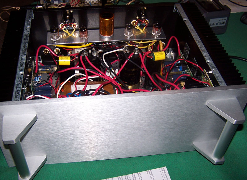
and here the photo of these tubes

For the test I have identified these tubes:
The Lundahl LL1660/PP has been configured with the turn ratio 2.25 + 2.25 : 1 to decrease output impedance.
The E82CC is near to the project limit because the Ra is a little to high.
Rout = ((( Ra + Rprim ) / 2 ) / ( 2.25 * 2.25 )) + Rsec =
= ((( 7700 + 625 ) / 2 ) / (2.25 * 2.25 )) + 68 = 890ohm (near the limit 1000ohm)
Ft(-3db) = Ra / ( 2 * 3.14 * ( Lpri / 2 )) =
= 7700 / ( 2 * 3.14 * ( 290 / 2 )) = 8.4 Hz (near the limit 10 Hz)
An automatic bias of tubes has been created with a single resistor for both the cathodes.
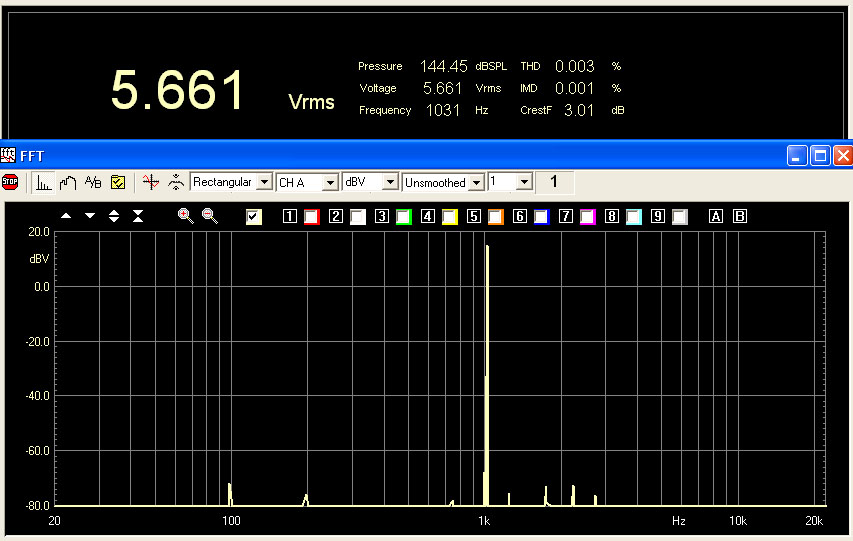
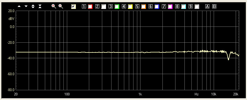
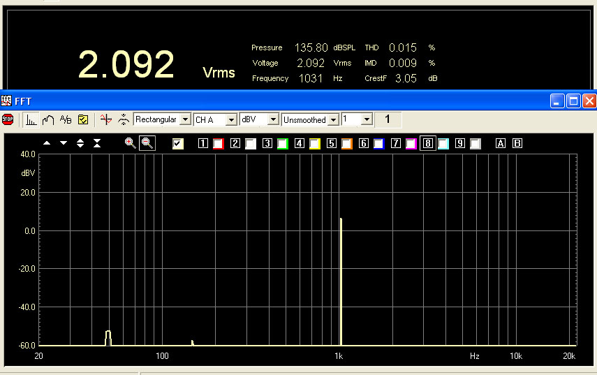
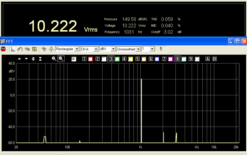
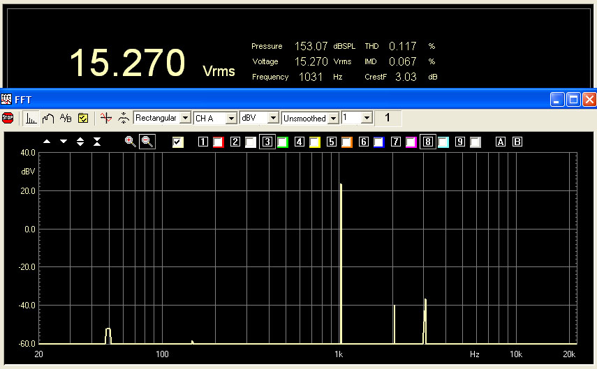
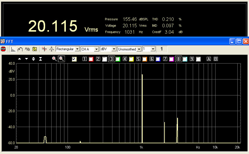
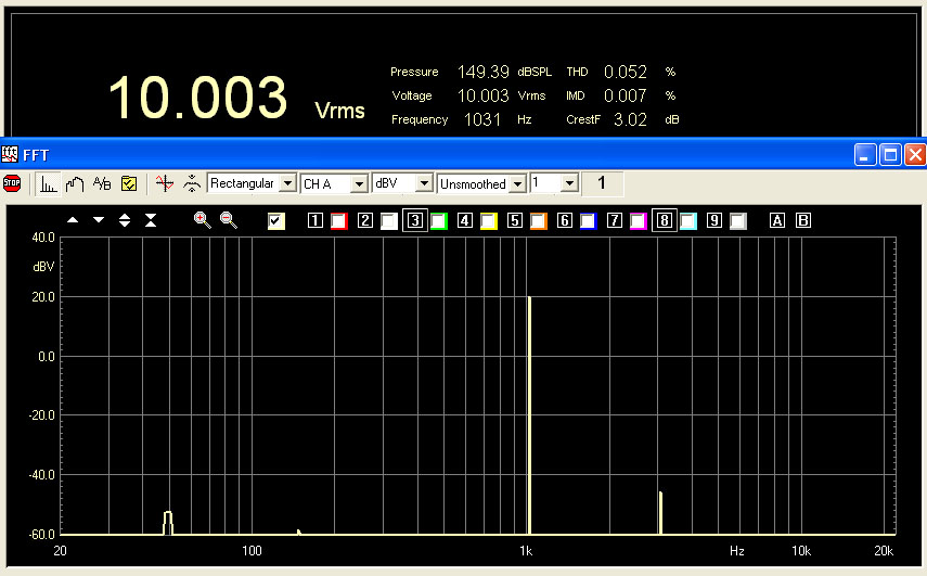
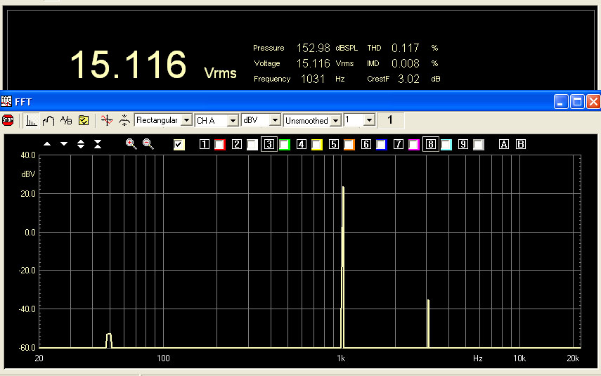
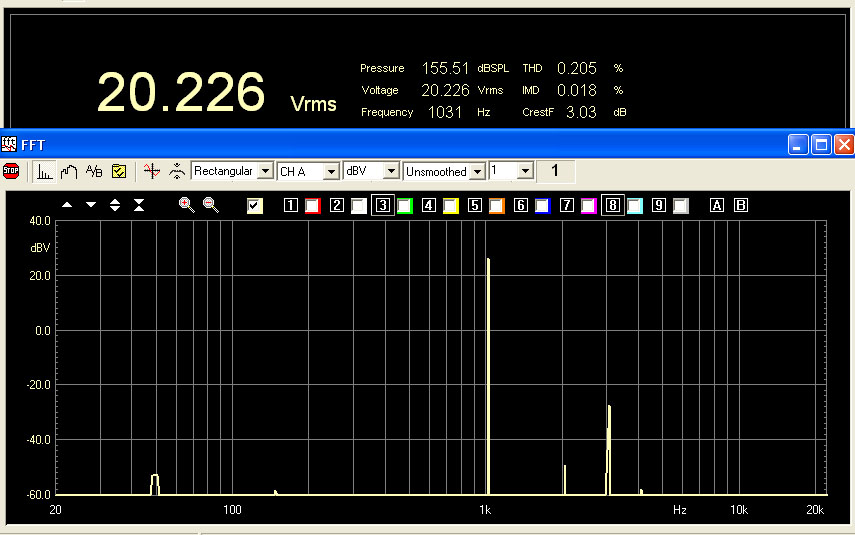
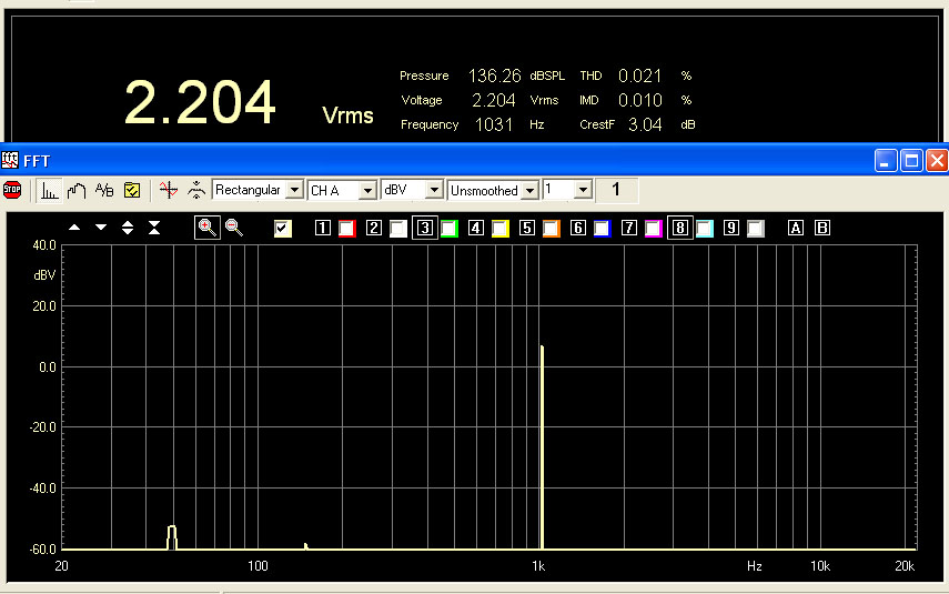
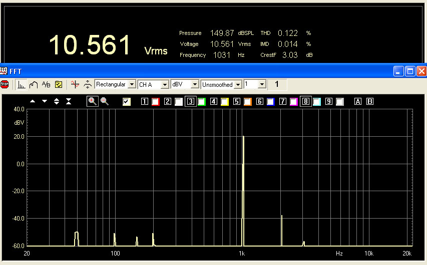
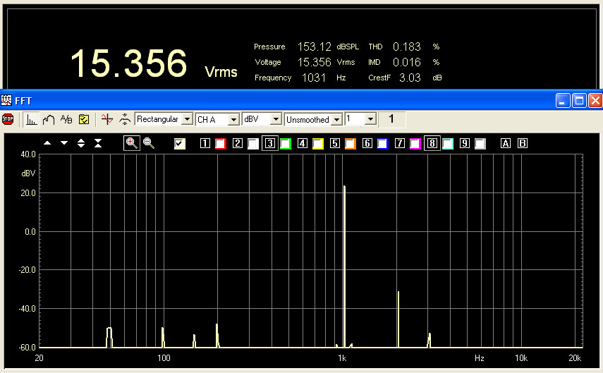
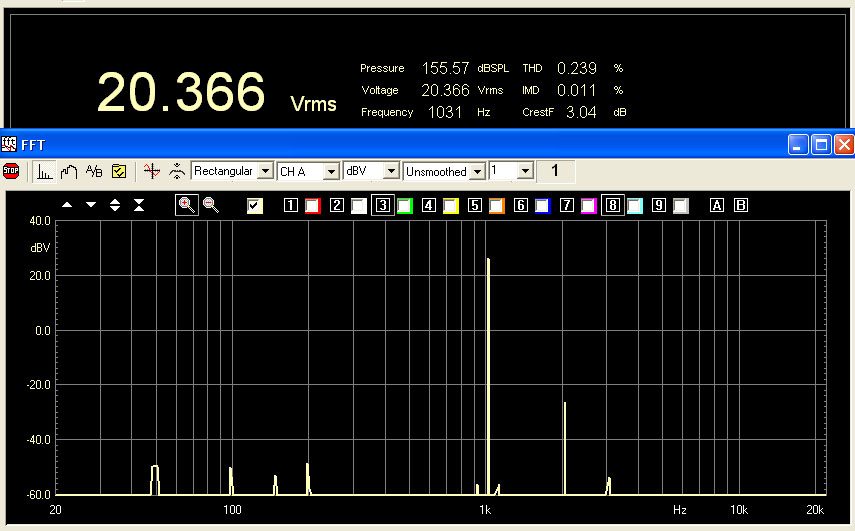
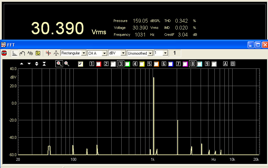
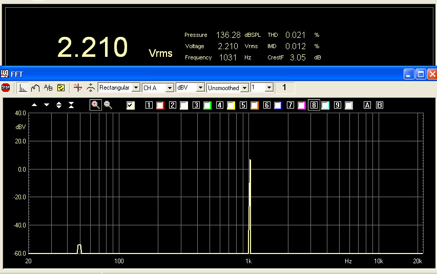
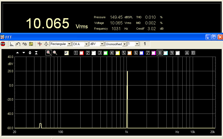
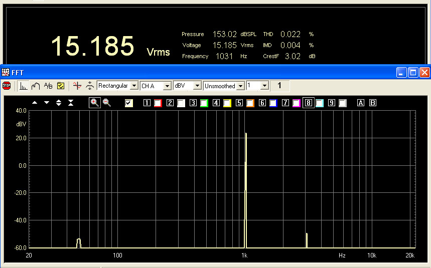
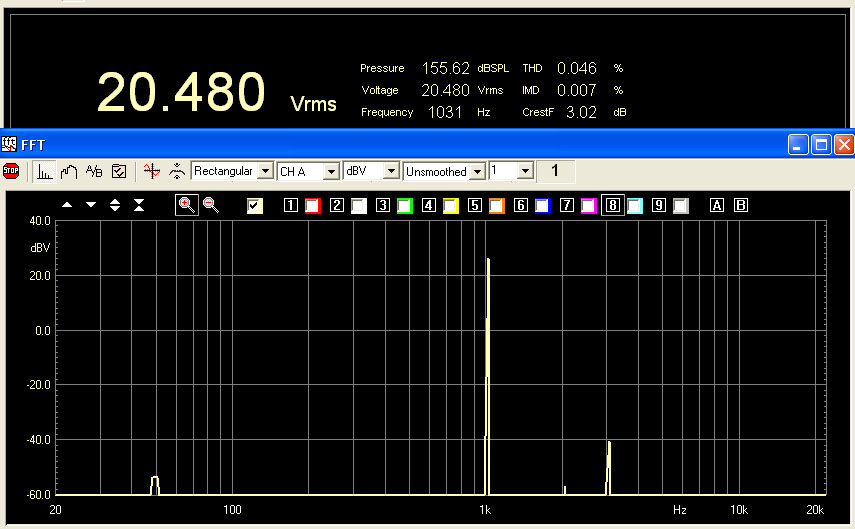
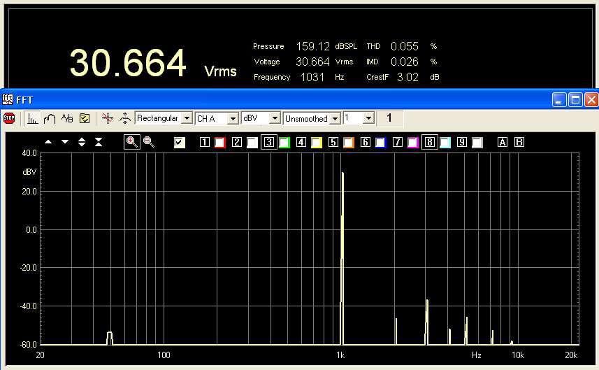
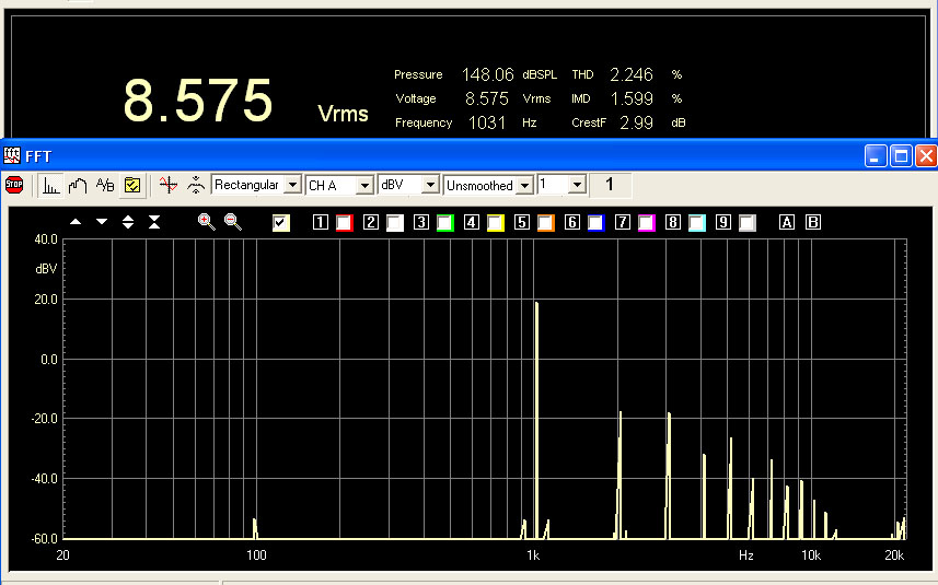
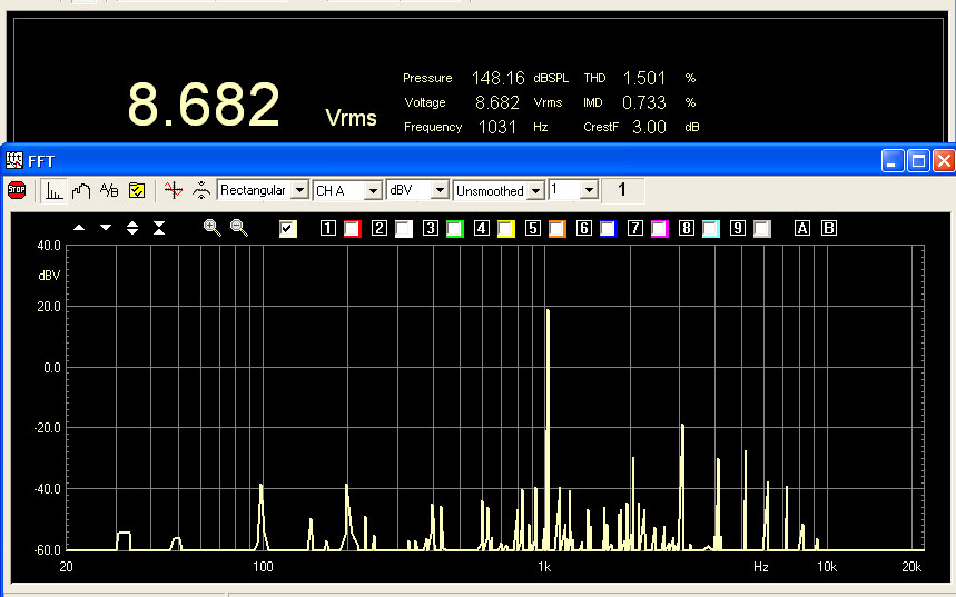
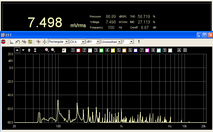
Follows the measurements result of these vacuum tubes. I have used my good Clio system (click on the value to see the plot).
| tube/output voltage | 2Vrms | 10Vrms | 15Vrms | 20Vrms | 30Vrms | Rk (ohm) |
| 5687 Jan Philips | 0.015% | 0.059% | 0.117% | 0.210% | 140 | |
| E182CC Mullard | 0.018% | 0.052% | 0.117% | 0.205% | 140 | |
| 5842 Raytheon chA | 0.021% | 0.122% | 0.183% | 0.239% | 0.342% | 37 |
| D3A Siemens as triode | 0.021% | 0.010% | 0.022% | 0.046% | 0.055% | 37 |
The D3A are incredible but we still need to compare the sound.
The output impedance measured is in the range from 290 to 326 ohm so very good to drive the high input capacitor of power mosfet.
CURRENT AMPLIFIER STAGE (comp. 6 & 7)
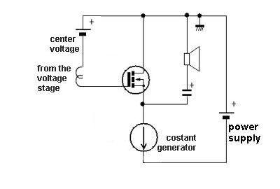 |
It seems a silly and common circuit but it has got great differences from any other similar design, that’s why this is unique. We have a typical source follower (as an emitter follower but with a Mosfet) working in pure class A with a current generator.Please note that this circuit works only in pure class A, so it requires enough bias current for the requested output power. The final schematic is very similar to the design here on the left. |
In my design the first feature making a big difference in the sonic results is the negative power supply and the signal ground tied to the drain of source follower.
With this design we achieve:
The
discoupling
of
the signal current from power supply because
the current generator has a huge impedance (an open circuit for the signal,
in theory)
The
constant current flow from the power supply
also during the music peaks that prevent any stress of the power supply.
The simmetric distribution of the power dissipated under static and dynamic conditions both on the current generator and the source follower, so I have used the same type of devices
In my first Power Follower I have used the IRF150 because they was cheap and easy to find in an electronic components shop near my office.
Now if we analyze the market there are many choices about these mosfet (click on the model to download the complete datasheet).
| mosfet model | Power dissipation (W) | Vdss (V) | Idrain (A) | Rds-on (ohm) | Input capacitance (pF) | Case |
| IRFP150 | 230 | 100 | 41 | 0.055 | 2800 | TO-247 |
| IRFP150N | 160 | 100 | 42 | 0.036 | 1900 | TO-247 |
| IRFP150V | 140 | 100 | 47 | 0.024 | 3130 | TO-247 |
| IRFP140 | 180 | 100 | 31 | 0.077 | 1700 | TO-247 |
| IRFP250 | 190 | 200 | 30 | 0.085 | 2800 | TO-247 |
| IRFP250N | 214 | 200 | 39 | 0.075 | 2159 | TO-247 |
| IRFP260N | 300 | 200 | 50 | 0.040 | 4057 | TO-247 |
| BUZ900CDP | 250 | 160 | 16 | 900 | TO3PBL | |
| BUZ900P | 125 | 160 | 8 | 500 | TO-247 | |
| 2SK1529 | 120 | 180 | 10 | 700 | 2-16C1B | |
| 2SK1530 | 150 | 200 | 12 | 900 | 2-21F1B | |
| GT20D101 (IGBT) | 180 | 250 | 20 | 1400 | 2-21F1C |
All devices with a max power dissipation lower than 180W has been excluded because the my target is a bias point at 4A with a power supply voltage of 40V so 160W on max peak.
It is possible use more mosfet in parallel configuration to get more power but this configuration can generate parasitic oscillation. To eliminate this problem it is necesary add resistors on gates and cross the finger.

 |
The IGBT have good
electric characteristics and low distortion also in normal class AB
operation because it is composed by a mosfet and transistor in a local
feedback configuration (click on design to enlarge).
I have used these many many years ago with good results in an hybrid class AB amp. but there is no vantage to use IGBT in class A operation. |
So in the table I have put in evidence with yellow characters the valid choices.
The BUZ series are produced by Magnatec and these device has been designed especially for audio amplifier applications instead of IRF specialized for switching application. If compared with IRF, of same power, the BUZ have also a lower input capacitance.
As output capacitors there are very few choices to get max performances:
The value of this output capacitor should be about 6800uF to 10000uF to get a low frequency cut-off about 5Hz with 4 ohm load.
Ft low(-3db) = 1 / ( 2 * 3.14 * 6800E-6 * 4) = 5.85Hz

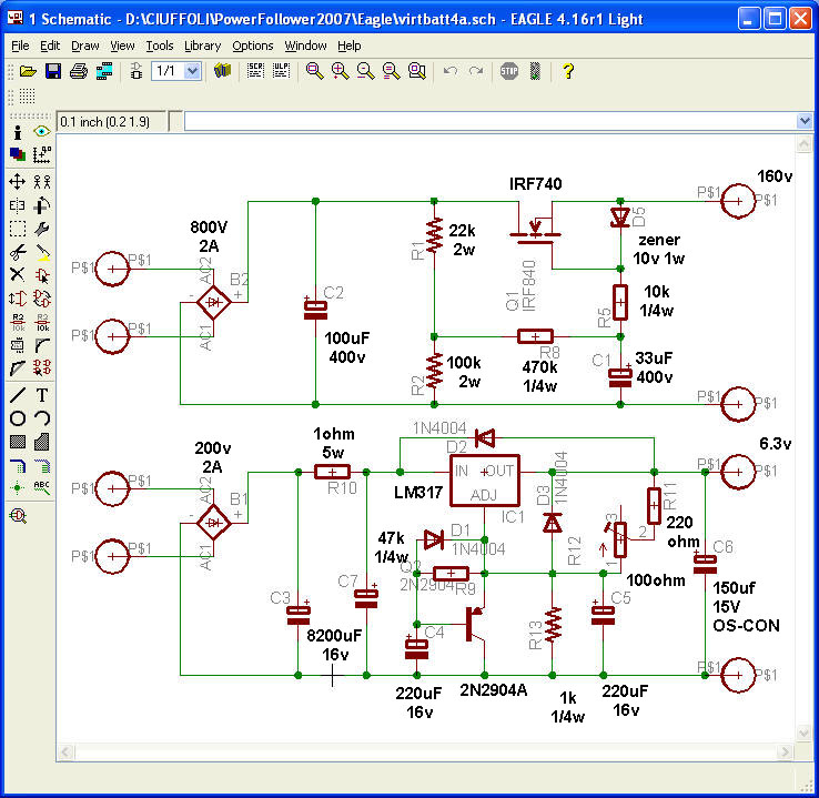
This simple design could be build on air with Twist Eye Terminals like the GrennanAudio but I prefer a good PCB using solid state device.
For the first time I have used the freeware version of Eagle schematic capture and printed circuit board design package.
All the pcb has been build by Olimex Ltd in Bulgara. They can receive also the Eagle files by email.

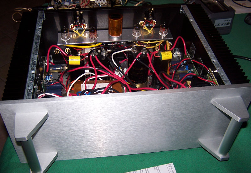
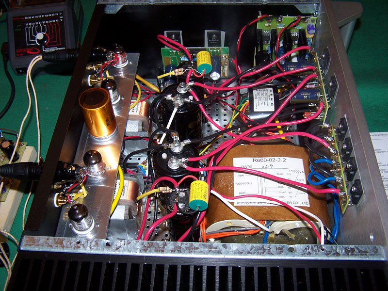
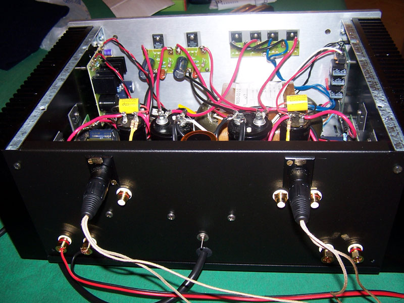
The case is the "Pesante Dissipante" model 04/400 Silver 10mm of Hi-Fi 2000 with 2 black oxidised lateral dissipators to get an Rt°C/W about 0,31 buy at Audiokit.
I have used in all the measurements the Clio system by Audiomatica with the Transit by M-Audio to use the USB port of my portable pc instead of the PCI audio board and to increase the resolution.
POWER SUPPLY FOR THE VOLTAGE AMPLIFIER STAGE
To get the max sonic performances has been choised slow turn on power supply for the filaments uning a common LM317 and a virtual battery operation power supply for the anodic using a power mosfet.
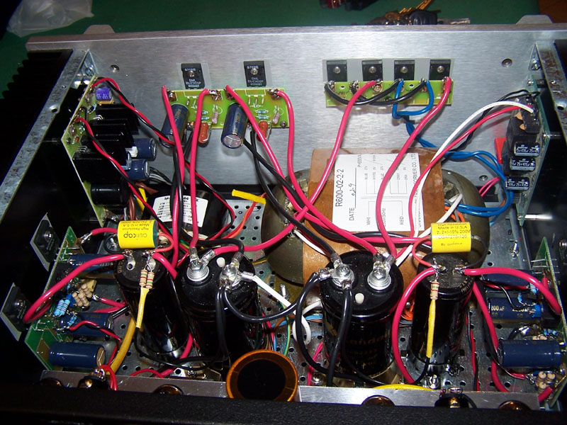
For this power supply I have used the R-CORE model R26-90 by DiyClub.Biz with primaries 2 x 115v and seconaries 0-150v(0.2A) + 2 x 0-9v (1.1A).

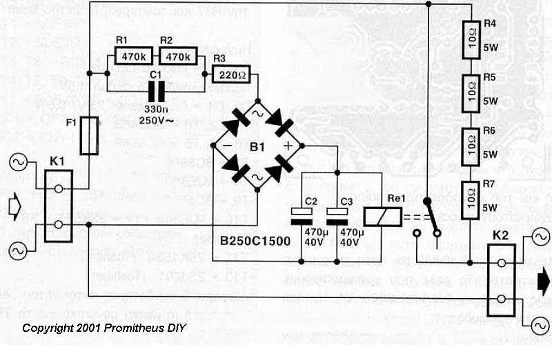
SOFT TURN-ON ON POWER SUPPLY
In my amplifier I have used a soft turn-on circuit to prevent shock to my house electric environment.
The circuit used in this amp. is a board got many years ago from AVONDALE but it is possible use a similar and simpler circuit like this on:
http://mitglied.lycos.de/Promitheus/delay_circuit_for_toroids.htm
SETTING BIAS POINT
In this amp. there are 2 trimmer to set with a simple voltage meter:
The first one should be set for the max dynamic range to have half of power supply voltage on fuse.