INTRODUCTION
This an "End" level design so, like the
Phono End
and DAC End, it
give the max sonic performances.
Now you may be perplexed about a hybrid design if you are a purist of vacuum
tubes but I tell you all my friends are shocked by the result of this amplifier.
In a direct comparison with the my new
813-GM70 SE,
the Hybrid 2010
version 2 and the
PP2010, the difference is huge and it is very difficult to return to hear
these other amplifiers.
All sounds are clear and detailed with incredible speed issue that leaves you
speechless.
In the past 20 years I have made dozens of amplifiers with different topologies,
but the results obtained with this was totally unexpected and unexplained.
I suggest this project to all those who want a definitive amplifier because it
can be used to hear any kind of music and it drive any kind of loudspeakers without problems
(multi-way and full-range).
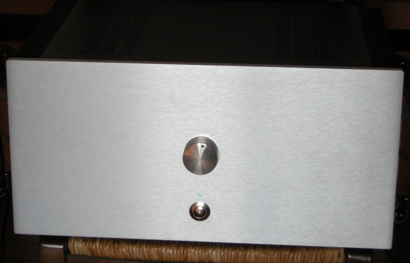
A great experience is not required for this project because the assembly is very
close to an electrical system rather than an electronic amplifier.
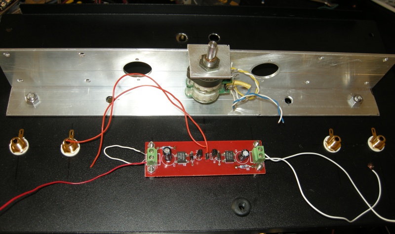
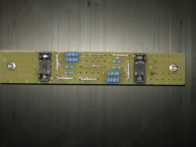
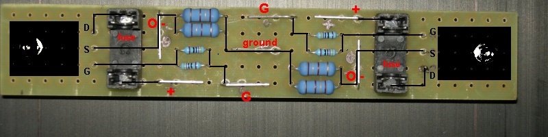
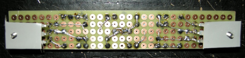
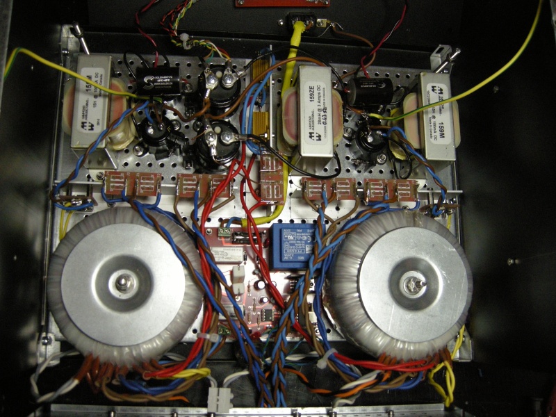
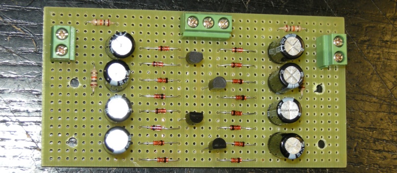
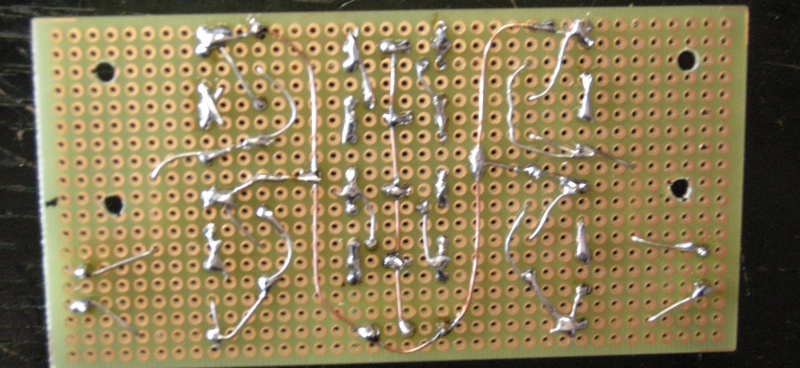
A pcb is only necessary for the protection circuit, but you can buy an
assembled
module and modify it.
Also if the
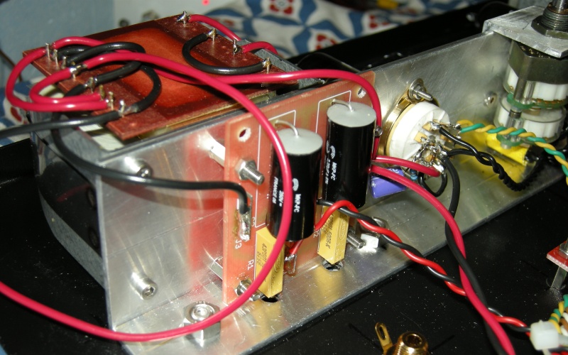
Circlotron output
stage avoid high dc output voltages in case of mosfet fault I suggest the use of
a protection circuit like in my all solid state design.
There is the possibility to reduce and increase the output power with very
simple modifications in the transformers and in the heatsinks.
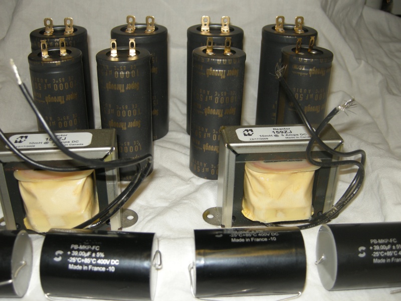
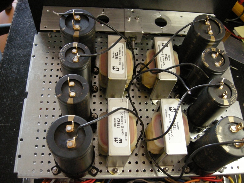
The majority of benefits are available even implementing this project in a
simplified version with a cheaper power supply (no chokes for the output power
section).
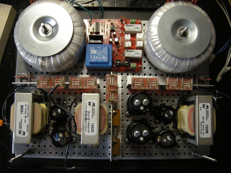
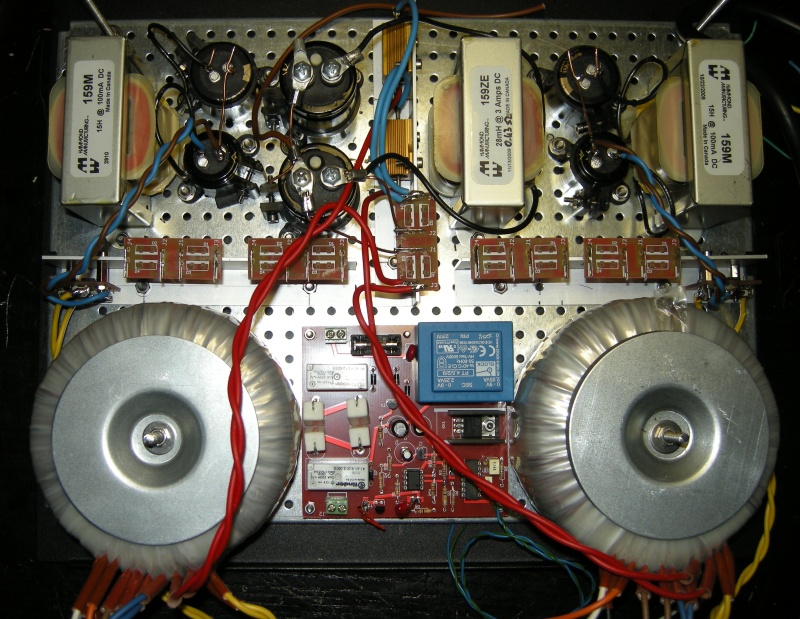
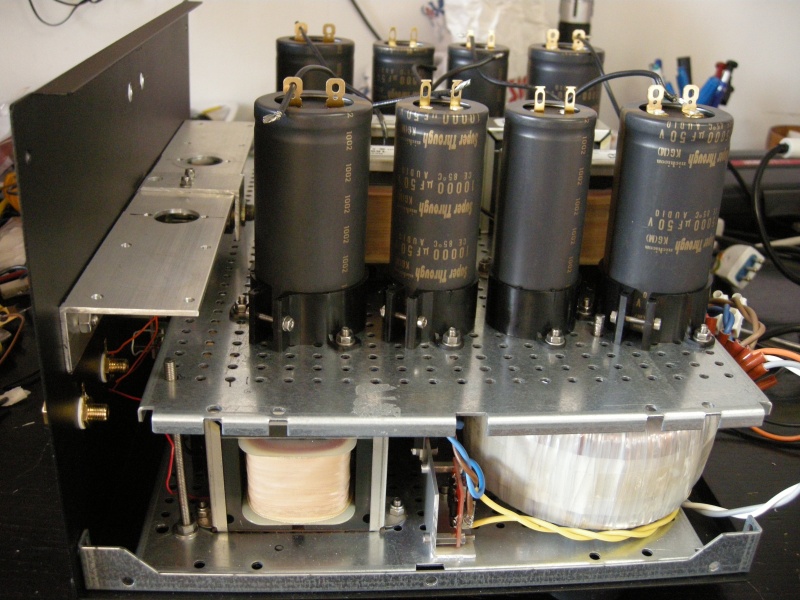
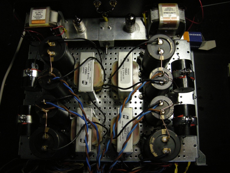
Using a CLC (capacitor, choke e capacitor) power supply is possible skip any
problem of noise and spikes generated in the rectifier.
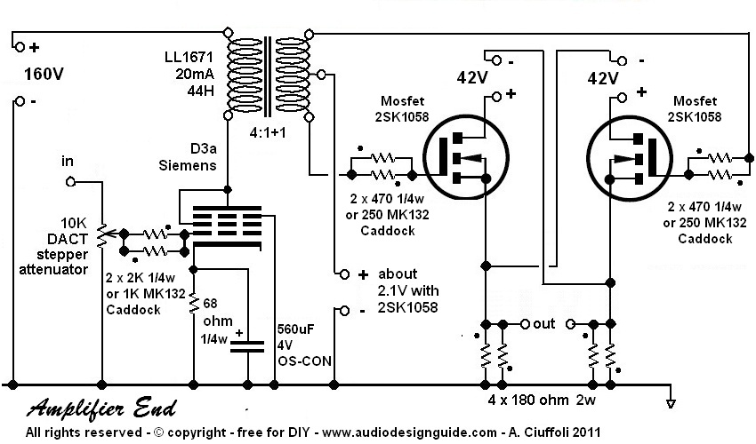
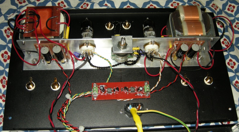
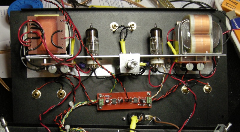
In the driver section you can decide to use the Siemens
D3a (hi-end
pentode to use in triode connection) or the Russian
6C45
(pure triode).
Both these tubes give a very similar sound performances and it is impossible
decide which is the best.
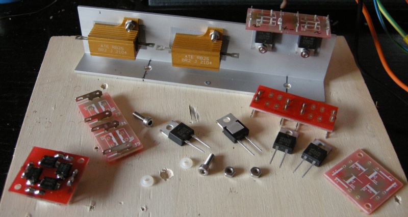
The test
show as best mosfet to use the
ACD100NSD and the
2SK1058
(attention to the fake on Ebay).
In these last years many person prefer to see circuit with the new
depletion mode mosfet
instead of enhancement mode but the linearity of the depletion is necessary only
when the mosfet is used as voltage amplifier (drain output) like the
Nelson Pass F5,
in my amplifier the mosfet are a follower (source output).
To use the depletion mode mosfet is necessary add a thermal compensation in the
bias circuit.


