back to my home page and other projects
OTL, Output Trasformer Less Tube Amplifier
Designed by: Andrea Ciuffoli.
contact me for any problems or question: webmaster@audiodesignguide.com
Specifications:
overall NFB less than 10db (usually kept as low as 4.5db with 90 dB/m
loadspeakers).
Gain about 26db in close loop mode.
Rout about 1 ohm Vout = 20Vpeak on 4 ohm load.
Very long life bias for 6C33C-B (only 0.2A).
I use such a setup with normal loudspeakers and with my Beyerdinamic
DT990 earphone. It could be a good choice to drive an ESL loudspeaker.
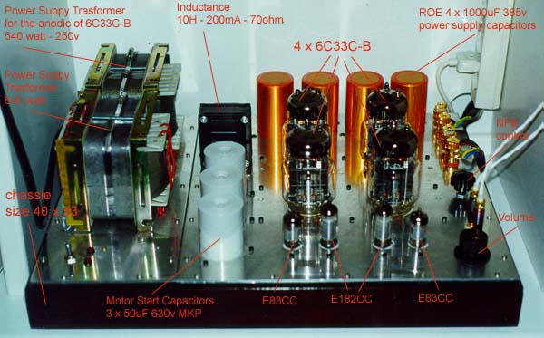
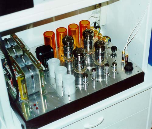
The power stage has been designed to work in a SEPP (Single Ended Push
Pull) configuration.
Design Issues
In my opinion the bigger problem encountred with the SEPP configuration
is due to the unbalance of the amplification factor between the output
tubes (upper and lower).
To overcome such a trouble, my choice was for the Technics configuration:
Technics
simplified schematics (email by Takuji Yamamoto)
until version 8.0a but now I have choices the VARIATION ON THE FUTTERMAN
as show in a
good article on
OTL Amplifier Background
I don't like the Circlotron (some problems here)
Now online the last versions:
Double power only duplicate output tubes!
Better drive to any load (loadspeakers or earphone)
Lower output resistence
Lower distortion
Lower power supply stages
Lower components
Lower local feedback
Zero noise
Only tubes on signal (no FET)
Output capacitor less design possible
Picture of the version 8.2 cheap & easy but same sound of the others
Picture of the version 8.2 OCL(8/8/98)
Picture of the version 8.2 (6/8/98)
to increase gain put a capacitor 220uF 16v
ELNA Cerafine only on 680 ohm of 2 stage
Is the OCL (Output Capacitor Less ) design real ?
old versions
version 1.0
version 6.0
version 7.0
Some plot by simulation on Version 5.0
frequency response with nfb = 5db - ft(-3db) = 135KHz
frequency response with nfb = 13db - ft(-3db) = 222KHz
Rout with nfb = 5db - 2.5 ohm
Rout with nfb = 13db - 1.47 ohm
Some photo
photo1
photo2
For tubes datasheet ask me or search on Internet.
  To see other OTL designs
  To look about an ultra cheap power supply
Important email messages related with this project:
from Kevin Kennedy
from Takuji Yamamoto
from Sovtek
from Roman Efimov (Odessa, Ukraine)
Single Ended Pure Class A Power Follower Amplifier
see new webpage on: http://www.audiodesignguide.com/PowerFollower/
The End Millennium
This is not a my design and I don't like assemble the kit of other people but
when I have seen this project.....
This is a complete push-pull amplifier in class AB operation without any feedback.
To get low distortion by the transistors in the voltage stage a simple but good
solution has been used. Infact an emitter follower is used after any voltage
amplifier to have low load for this one.
Other characteristics of this amplifier are:
the signal street on the board is very short
output device are the best Sanken transistors
high capacitors value used in power supply 120.000uF
Separated voltage stage power supply
Balanced or unbalanced input is allowed
Many components are preasseblated (all the SMD)
Top quality bypass capacitors are used in power supply (Music cap)
Very large band DC to 500.000 Hz
High output current 46 Ampere for 1ms
Output power from 120watt to 250watt (depend by version)
DC servo control included
Short circuit protection included
You can buy only some parts of the kits
You need only a volume control as the CT1 of DACT to connect to a CDPlayer
I have tested this amplifier on some loudspeakers, also a type without caps. in the
filter with very low impedance and the result is in any case very good, never there
is distortion,the bass frequency are fast and controlled, the middle and high frequency
are clear on any kind of music from classical to hard rosk
to get more information go on L C Audio or contact by email: lcaudio@post5.tele.dk
Push Pull Pure Class A "Hot Follower 99" Amplifier
Designed by: Andrea Ciuffoli.
The target of this project is a 50W RMS on 8 ohm and 100W RMS on 4 ohm in Class A
Both input/driver stage work with the same bias so the Vbe distortion should be compensated!
The simpler design of the Coll Follower could be used!
Ofcourse also a normal capacitor/bridge only power supply could be used!
Must be driven by a voltage stage with min bias 30mA
WARNING: designing phase so some parts could be change in the next days!
Ofcourse this design cannot give the same sound of the reference: "Power Follower 99"
Push Pull Pure Class AB "Cool Follower 99" Amplifier
Designed by: Andrea Ciuffoli.
This is a 100W RMS (8 ohm) Pure Class AB Amplifier with original design never seen!
Both input/driver stage work in optimal Class AB (100mA for each devive)
Ofcourse also a normal capacitor/bridge only power supply could be used!
Must be driven by a voltage stage with min bias 40mA
WARNING: designing phase so some parts could be change in the next days!
Ofcourse this design cannot give the same sound of the reference: "Power Follower 99"
Different level distortion simulation
This plot has been created with a my custom version of spice3f4.
Different frequency distortion simulation
This plot has been created with a my custom version of spice3f4.
Limitation of Cool Follower
This plot show the limitation of the Cool Follower!
Input current
Winsurfing, my preferred sport
photo 1
photo 2