 In its original design, the loudspeakers are very ineffective (70-72 dB SPL).
The hardest part is to get the materials, depending on how much time you use
on experiments with the magnets, the membranes, the MDF wood plate design, the membrane design, etc.
In its original design, the loudspeakers are very ineffective (70-72 dB SPL).
The hardest part is to get the materials, depending on how much time you use
on experiments with the magnets, the membranes, the MDF wood plate design, the membrane design, etc.
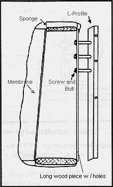
1- Cut the wood pieces, one the mirror image of the other.
2- Resonance damping of the woofer hole of the MDF plates, just the
top and bottom side of the hole, don't choose a very thick sponge, it'll
be very hard to stretch the membrane if its to thick, and wrinkles will
be an unavoidable part of your design, not so nice... Cut the tweeter hole
considering the magnets dimensions, the metal plates that cover the inner
side of the hole, etc.
3- Arrange the metal plate design, cut a piece either to fit the woofer
hole or to be screwed directly to the back of your MDF Plate, you find out
what is best for your particular case. The tweeter hole needs a piece on
the back side too.
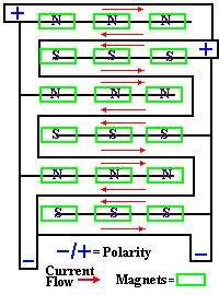
4- Put the magnets on in the desired design, all with due consideration
to the conductor design you've chosen, the length of conductor you need,
the resistance, the impedance (something I never considered, I just
measured the Ohm resistance, and calculated it to be 3 ohm). If you're
not as unlucky as I to have very weak magnets, there should be no need
to stick them on to the plate, their magnetic strength should be more than
enough, unless you plan to throw them around the house....
5- Design and create the membranes, more about that in the membrane section,
and the possible betterings of the design.
SWEAT, SWEAT, this is the tough part, so I feel...
6- The row of magnets in the tweeter section closest to the woofer must have
the same polarity as the top row of magnets in the woofer section. The
tweeter magnets are double, boosting the magnetic field strength.
7- The conductor design: This speaker system uses the collective principle.
The current must flow in the same direction for all conductors in the same
magnetic field. With respect to the woofer conductor, it's necessary to have
an unbroken conductor, that covers the membrane so it moves as a single
flat surface. This design has two conductor strips, in a serial disposition.
The way the conductors transmit the current is always in the same direction
and this creates a force that is either inward or outward, deppending on the
current direction with respect to the magnetic field. (In my project I used
aprox. 68 windings of the conductor). The total length of the aluminium
conductor in the original project was 18 meters x 9 mm. (30 micrometers in width) and
having a 3 ohm resistance.
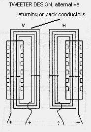
The tweeter conductor was originally built with four conductor coils, as
shown in the figure, this makes the resistance
larger, the conductor is 9 meters long and half the width, 4.5 mm, thus 3 ohm
resistance. The membrane should be corrugated, (now that I think about it
I don't know why...) thus the length shrinks aprox. 10%.
8- Crossover and speaker connections: The woofer and tweeter are connected
in parallel. Serially connected to the woofer you put a coil (0.95 mH),
and serially connected to the tweeter a condensator, 105 microFarad.
The speakers impedance is aprox. 3-4
ohms, very frequency linear.
9- The speaker feet, build them either out of the same wood, held by strong
shelve angles or build a more sophisticated design.
10- Check if things are alright. Check out if there should be any short
circuits with the multimeter, check if there are any missing connections too.
the resistance measured at the speaker connections to the amplifier should
be aprox. 3,5 ohm. Now connect the amp............ See what can happen,
if all is well I assure you you'll have a hard time erasing the wide
and shiny smile you'll have on your face, once you've constructed such a
beauty out of such lowly materials, you'll need to do a number of adjustments
to the sound balance, I had no spectrum analyser, I just used my ears,
the best instruments I have at my disposition, adjust the balance between
the woofer and the tweeter by putting more or less resistance on the tweeter,
this will crave either more or less current from the amp, thus having more or
less treble, balancing the sound image accordingly.
11- HAVE LOTS OF FUN, I DID, AND STILL HAVE 5 YEARS LATER.