The second stage is a cathode follower used to decrease the output impedance and to drive the final stage with sufficient current.
|
back to www.audiodesignguide.com |
To get more information contact me at: webmaster@audiodesignguide.com |
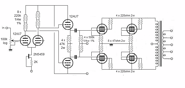
Follows the schematic of my first test to check the
quality of the output transformers in the most simple configuration: class A,
triode connection, no feedback.
The second stage is a cathode follower used to decrease the output impedance and
to drive the final stage with sufficient current.

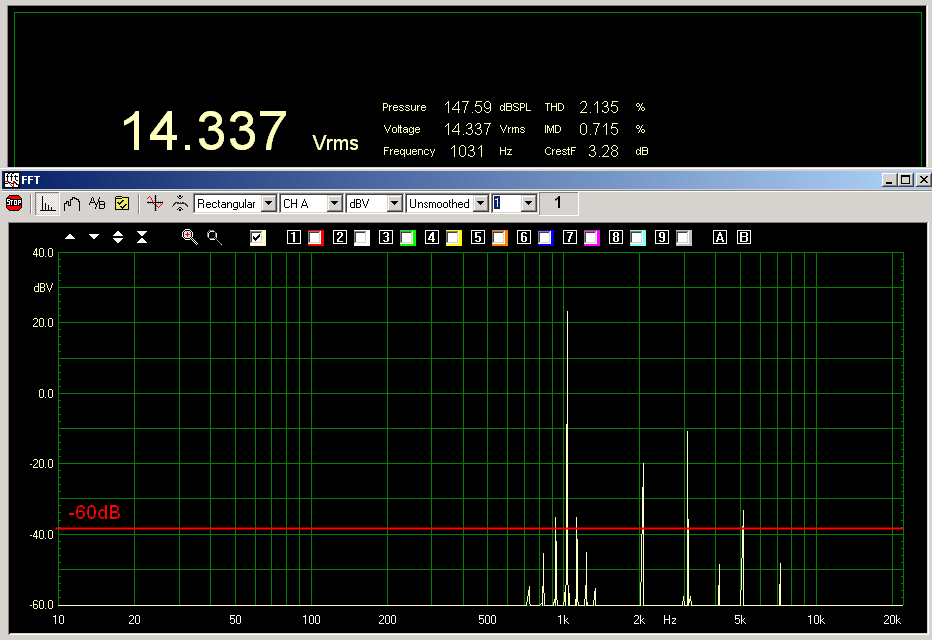
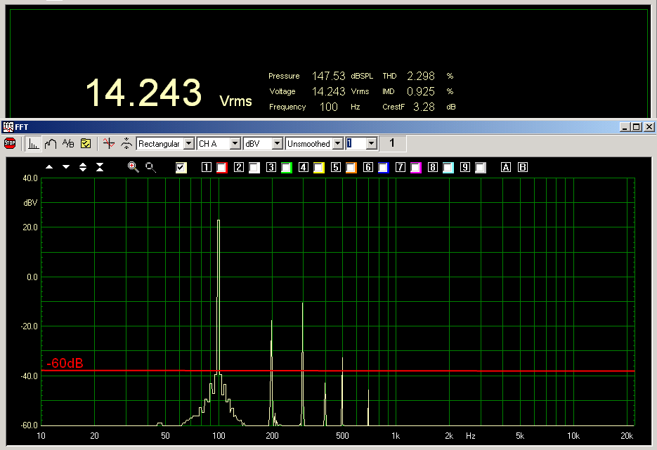
The result of this circuit are not bad:
Vout=14.337Vrms with only 2% thd so about 30w on 8ohm
Vin=0.767Vrms
Output impedance near to 3ohm
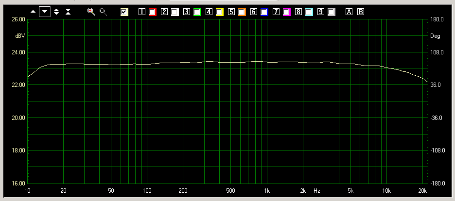
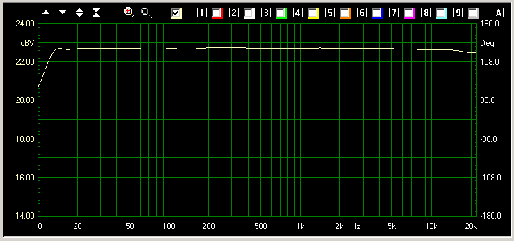
Frequency band 10-20KHz at -1db
Global feedback about 0dB
Va = 430v Ia = 42mA x 4
To reduce the output impedance it is possible use the transformer secondary on cathode feedback like use by AudioResearch and Bartolomeo Aloia.
Using this method the gain is reduced of 3dB and output impedance is near to 2ohm (see measurement test 2).
SCHEMATIC TEST 2
In the triode connection the power is limited and the damping factor is not
enough good also if we use the cathode feedback of the transformer secondary.
So I have decided to switch to the ultra linear connection also if this mean go
near to the pentode configuration with an inevitable increment of the internal
resistance of vacuum tubes.
Using this connection we get also more voltage gain in the final stage so the
cathode feedback of the transformer secondary compensate the increment of
internal resistance of vacuum tubes so the output impedance without a global
feedback is only about 4ohm.
If we decide to use global feedback it is necessary to get more voltage gain so
I have changed the first stage to a hybrid cascode adding a fet on input.
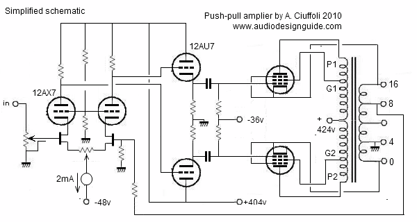
This new schematic give very good performances and add a little complexity.
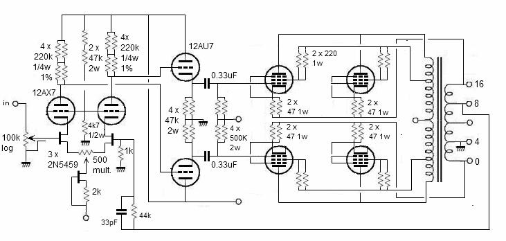
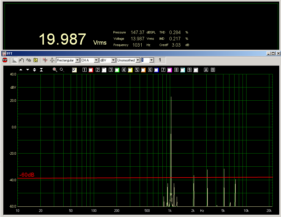
Measurement result:
Vout=20Vrms with only 0.3% thd so about 50w on 8ohm
Vin=0.700Vrms
Output impedance near to 0.7ohm
Frequency band 10-20KHz at -1db
Global feedback about 6dB
Va = 430v Ia = 42mA x 4
SCHEMATIC TEST 3
The previous schematic run very well but many persons can
prefer a pure vacuum tube configuration so I have decided to create a new design
inspired to the AudioResearch reference
amplifier but maintaining the good input differential stage.
The less common tube 5687 has been used but it can be replaced with few
modifications with the E182CC and the ECC99 present in the actual production.
The performances of this design has been optimized with
electronic simulation using the
WinSpice software for Windows.
The WinSpice 3.1
has been develop by Mike Smith and it is a beatiful port of original Spice3f4
develop by Berkeley University of
California.
It can generate waveform plots to individual floating windows and contains a
powerful scripting language.
In the direct comparison with the previous circuit in the simulation is visible a little bit
limited band due to the driver of final tubes with anode instead of cathode but
the audiophile person will see in this new schematic many others benefits for
the fet elimination and no strong local feedback in the driver stage.
The sound of this version is not pleasant and the reason of this should
be the low anodic voltage used on both stages to allow the dc coupling.
Using this circuit there was as an oscillation of the amplifier also without
global feedback so seen these problems I have decided to came back on the
original idea.
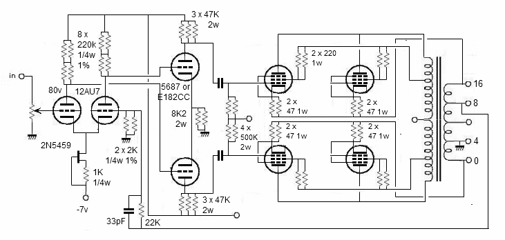
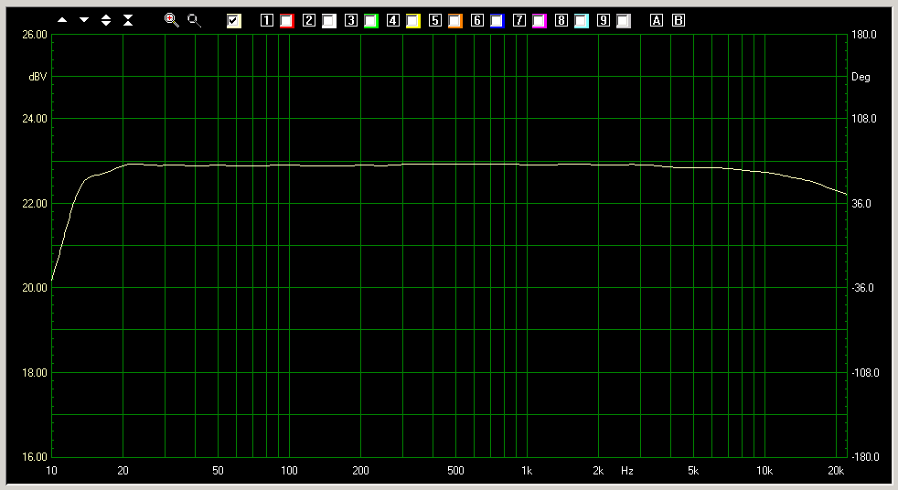
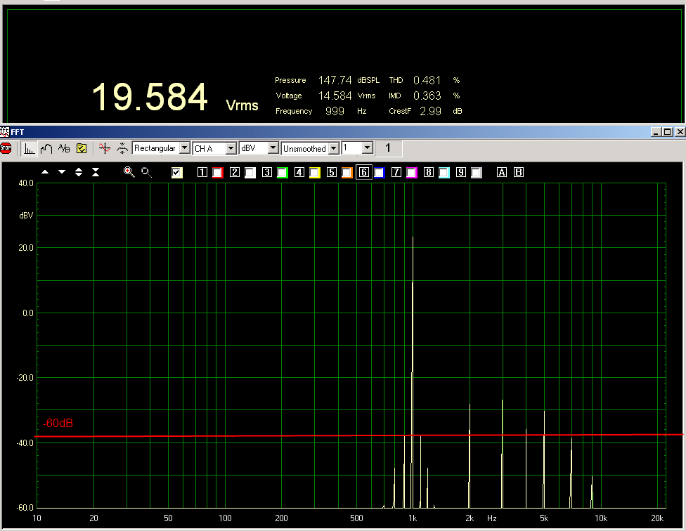
Measurement result:
Vout=20Vrms with only 0.5% thd so about 50w on 8ohm
Vin=0.666 Vrms
Output impedance near to 0.7ohm
Frequency band 10-20KHz at -1db
Global feedback about 4.5dB
Va = 430v Ia = 42mA x 4
SCHEMATIC TEST 4
To try to design a pure vacuum tubes amplifier I have
tested the following configuration where the fet used in the cascode has been
replaced with another 12AX7.
After many measurement tests the best result are obtain using the lower 12AX7 at
only 30v.
In any case the distortion and the sensitivity is worst of the version with the
fet.

Measurement result:
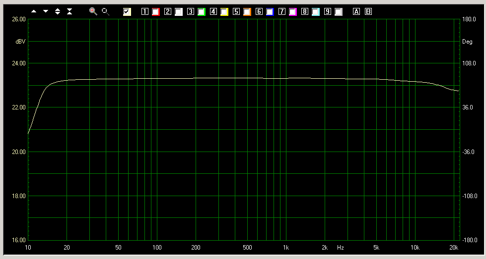
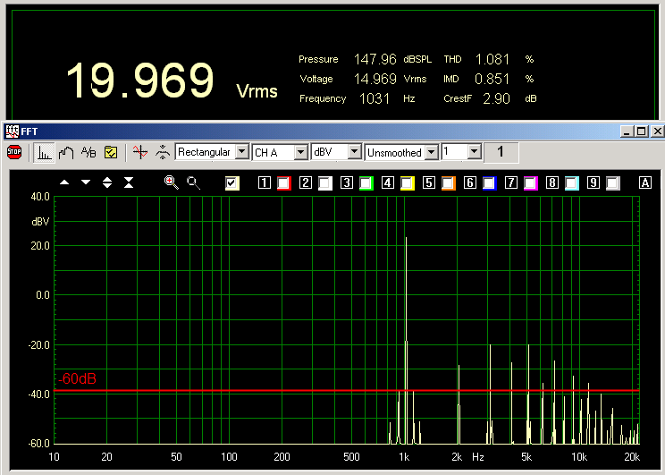
Vout=20Vrms with only 1.0% thd so about 50w on 8ohm
Vin=1.3 Vrms
Output impedance near to 0.7ohm
Frequency band 10-20KHz at -1db
Global feedback about 7dB
Va = 430v Ia = 42mA x 4
SCHEMATIC TEST 5

Measurement result:
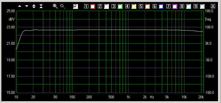
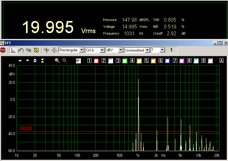
Vout=20Vrms with only 0.5% thd so about 50w on 8ohm
Vin=0.962 Vrms
Output impedance near to 0.7ohm
Frequency band 13-20KHz at -0.2db
Global feedback about 4.5dB
Va = 430v Ia = 42mA x 4
SCHEMATIC TEST 6
This new version has been optimized to get the best performances in
measurement and in the sound.

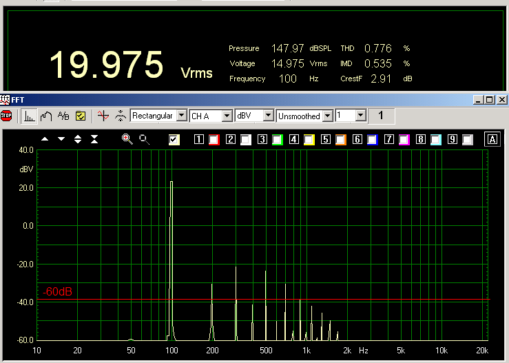
MEASUREMENTS TEST 1
Triode connections
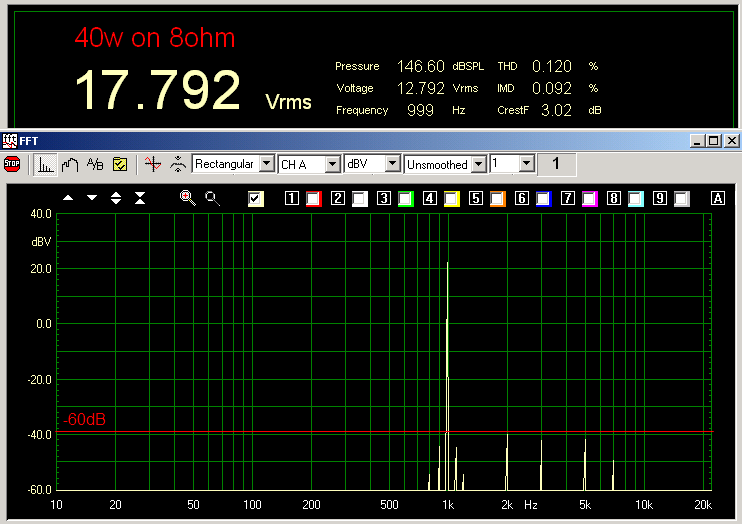
MEASUREMENTS TEST 2
ULtralinear + catode feedback at 50w without global feedback
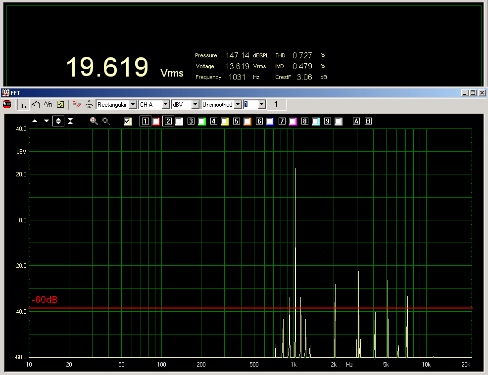
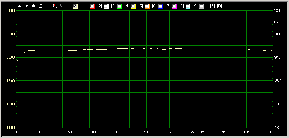
Ultralinear + catode feedback at 50w with a global feedback of only 6dB
MEASUREMENTS TEST 3
Ultralinear + catode feedback at 50w with global feedback of only 4.5dB
MEASUREMENTS TEST 4
Ultralinear + catode feedback at 50w with global feedback of only 7dB
MEASUREMENTS TEST 5
Ultralinear + catode feedback at 50w with global feedback of only 4.5dB
TEST SYSTEM


MATERIAL SOURCES
PHOTOS