
|
back to www.audiodesignguide.com |
To get more information contact me at: webmaster@audiodesignguide.com |
INTRODUCTION
After many years
designing single ended amplifiers I have decided to start a series of
test
about the Push Pull amplifiers.
These amplifiers are considered at a lower level than single ended but if you
want a power enough to drive ESL loudspeakers and low distortion systems like
Audiotechnology,
Dynaudio,
Scanspeak,
Morel and
Seas there is no other choice.
The main problem of Push-pull amplifier is the not perfect distortion decay with
the
cancellation of even harmonics but if
we keep the distortion level very low this consequence can be ignored and
the sound will not be affected.
Another
characteristic of many Push-pull amplifier is the high global feedback used to
get a good damping factor because to increase the output power often are used
output transformers with low turn ratio.
As my others amplifiers to preserve the signal I have used the minimum number of
components on the signal path so only one inter stage capacitor is present.
Here I would like to create a Push-pull taking only the benefits of this design
and
minimizing the bad effects.
This amplifier, like the my other designs,
can be connected directly to
a CD Player or to a DAC without using a pre-amp.
update 23 Feb 2016
Some modification by B-LAB of Stefano Bianchini
Vout=20Vrms with less than 0.5% thd so about 50w on 8ohm
Vin=0.962 Vrms to get 50w
Output impedance near to 0.5ohm
Frequency band 13-20KHz at -0.2db
Global feedback about 4.5dB
This amplifier give an incredible good sound on any
loudspeakers, tested on the my Monitor 2 e Hi-efficiency system.
TUBES
 |
To create a push
pull amplifier
is possible to use triode and pentode but obviously to test many configurations
like the ultra linear we need a pentode. There are many pentode good for audio amplifiers but the most common in the current production are the EL34, 6550 and the KT88 so follows a compare table with the main characteristics and price:
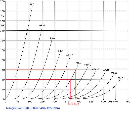
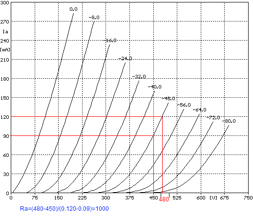
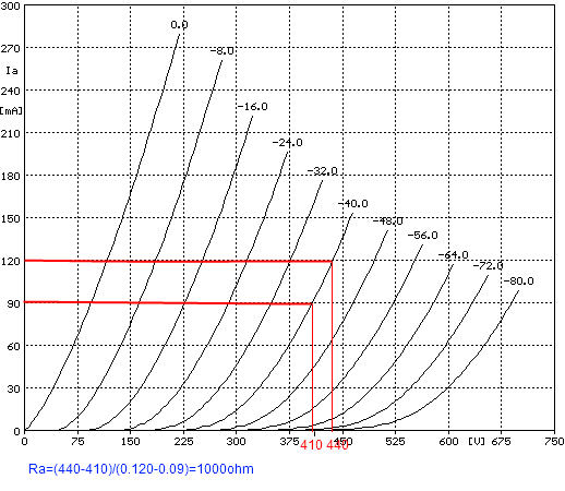
The
output plate
characteristics have been measured with the Sofia computer-controlled
curve-tracer by Audiomatica
and I have added the lines to calculate the internal/plate resistance. |
 |
 |
To get the best
result use matched quad tubes available in the shop
thetubestore.com or
pmcomponents.co.uk. As driver tubes I have used the Jan Philips series to get the best sonic result. In this amplifier it is possible use any kind of 12AX7, ECC83, E83CC, CV4004 and 12AU7, ECC82, E82CC, 5814 without change other parts. The power supply fix the filaments reference at +80v instead of 0v so to consider the max cathode to heater voltage. |
In the datasheet is mention this limit:
| tube model used | max cathode to heater voltage (max Vkf) | circuit cathode voltage (Vk) | heater voltage (Vf) | Vk - Vf |
| ECC83 / 12AX7 | 180v | 20v | 80V | 60V |
| ECC82 / 5814 / 12AU7 | 180v | 246V | 80V | 166V |
| EL34 | 100v | 1V | 80V | 79V |
The circuit cathode voltage (Vk) is calculated with:
EL34 current = 46mA
Resistance on cathode = 47 // 47 = 23.5ohm
Cathode voltage = 23.5ohm * 46mA = 1V
ECC83 current 1mA
Cathode voltage = 20V
ECC82 current 6mA
Resistance on cathode = 82K // 82K = 41Kohm
Cathode voltage = 41Kohm * 6mA = 246V
ECC83 and ECC82
sockets, bottom view.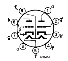 |
EL34 Socket, bottom view
|
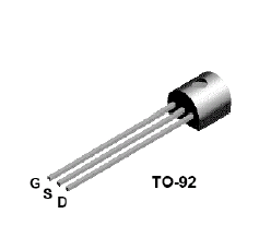
2N5459 pin
|
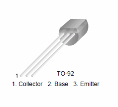
BC546B pin
|
TRANSFORMES
![]()
2 x Bartolucci 557E
Nominal power 50w
Primary impedance 4500 ohm
Primary Inductance 36 H
Primary resistance 64ohm
Weight 4 Kg
Secondary grid at 40%
1 x Bartolucci
Nominal power 400w
Primaries: 2 x 115v
Secondaries:
2 x 350v 0.4A
2 x 6.3v 9A
1 x 100v 0.1A
The price for the complete set of these
transformers is about
400 + tax 20% (3 item).
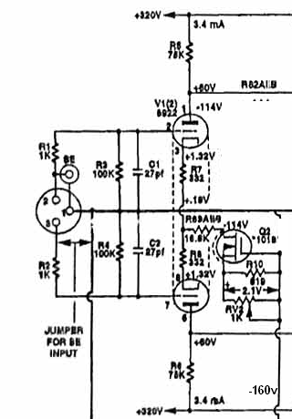
PHASE INVERTER
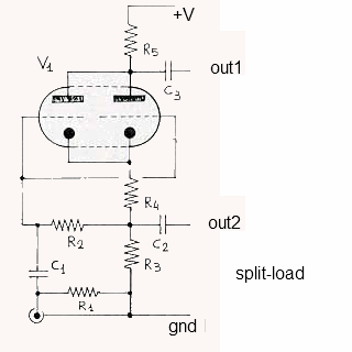 |
In all the push-pull amplifiers is necessary a phase inverters to split the unbalanced input signal into two balanced signals out of phase by 180 degrees to drive the push-pull output tubes. The performances of this phase inverters is very important and it affect the final result of the amplifier. Most push-pull amplifiers use the the split load or the paraphase but both have a lot of disadvantages.
The split load without a regulation
give two precise outputs with the same level but the output
impedance are completely different so it should not be used to drive
directly difficult load like the final stage. These first two schematics are parts of Bartolomeo Aloia amplifiers. To get the best performances
with the minimum
components I have decided to use the differential stage seen in the most
of solid state amplifiers. |
 |
|
|
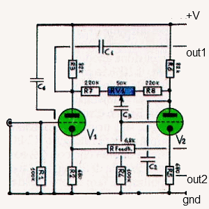
SCHEMATIC

In the triode connection the power is limited and the
damping factor is not enough good also if we use the cathode feedback of the
transformer secondary.
So I have decided to switch to the ultra linear connection also if this mean go
near to the pentode configuration with an inevitable increment of the internal
resistance of vacuum tubes, see test here.
Using this connection we get also more voltage gain in the final stage so the
cathode feedback of the transformer secondary compensate the increment of
internal resistance of vacuum tubes and the output impedance without a global
feedback is only about 4ohm.
This output stage design with both cathode feedback and ultra linear is inspired
to the AudioResearch reference amplifiers.
To have enough voltage gain to use global feedback
I have inserted in the first stage to a hybrid cascode with vacuum tubes and fet.
The input fet used in this amplifier create a very good result maintaining a
simple design and this should not persuade
you to love this design.
It is possible see in many AudioResearch
vacuum tube reference amplifiers the fet in input stages.
This driver stage give these performance:
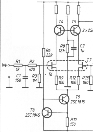
PCB
The driver stage of this amplifier is a little bit complex so I have decided to create a pcb
using Eagle Cad.
Follows the schematic of all the parts included in the pcb.

R1,R2,R4,R5,R30,R37,R38,R47= MF50 470K 0.5W 1% cod. Farnell 934-0645
R21,R22,R23,R24,R61,R62,R63,R64 = MF50 220K 0.5W 1% cod. Farnell 934-0220
R11,R12,R51,R52 = 1Mohm 1% 0.25W
R7,R32 = 100ohm 1% 0.25W
R9,R50 = 22K 1% 0.25W
R6,R8,R48,R49 = 1Kohm 1% 0.25W
R13,R14,R53,R54 = 2Kohm 1% 0.25W
R15,R16,R55,R56 = 47Kohm 1% 0.25W
R25,R26,R65,R66 = 27Kohm 1% 0.25W <<< reduced
to have about 20-22V max on jfet drain
R17,R18,R19,R20,R57,R58,R59,R60 = 82K 2W
R39 - R46,R73 - R80 = 2Kohm 1% 0.25W
R3,R31 = 500ohm multiturn trimmer Spectrol 64
R10,R36 = 1Kohm multiturn trimmer Spectrol 64
R29,R33,R69,R70 = 10Kohm multitrun trimmer Spectrol 64
R81,R82 = 6800ohm 2W
C1,C3 = 22pF ceramic or silver mica
C9,C10 = 470nF 250V PHE426 MKP cod. Farnell 157-2144
C2,C4,C5,C6 = 0.68uF 630V Jensen copper film paper in oil
CX1,CX2,CX3,CX4 = 1uF 250V PHE426 MKP cod. Farnell 157-2145
C7,C8 = 100uF 200v any electr.
V1,V3 = 12AX7, ECC83, E83CC, CV4004
V2,V4 = 12AU7, ECC82, E83CC, 5814
Q5,Q6 =
2N5459

DRIVER MEASUREMENTS

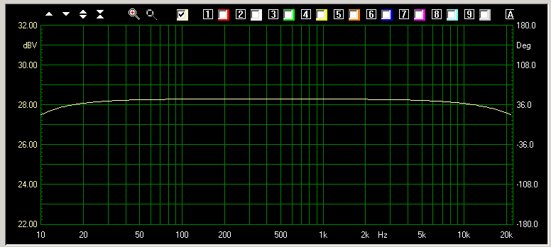
FINAL MEASUREMENTS


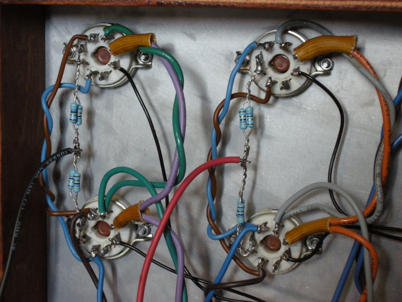
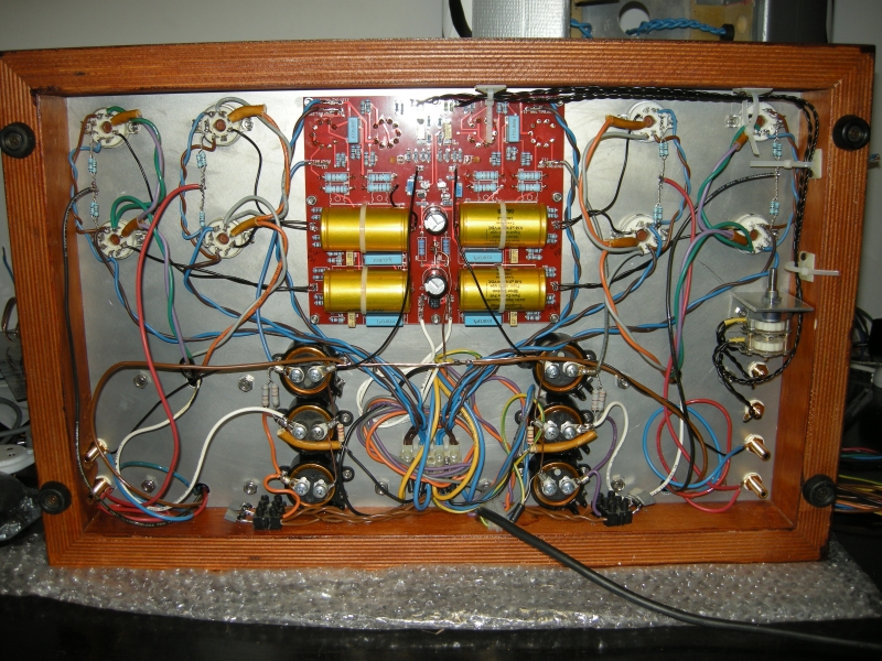
PHOTOS


TEST SYSTEM


MATERIAL SOURCES
