


|
back to www.audiodesignguide.com |
To get more information contact me at: webmaster@audiodesignguide.com |
Hybrid Class D system and new DAC
Output stage
Gen
2025
Click on Hi-End Hybrid Class D system to see this true reference hi-end system.
INTRODUCTION
This is a fully balanced and differential
DAC output stage that I designed many years ago for an Italian company.
The main features
are simplicity, very good sonic performances and perfect instrumental
measurements.
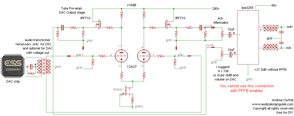
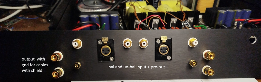
This circuit can receive as input balanced or un-balanced signal and
convert both to balanced so is perfect also like a pre-amplifier.
It can be
used with many DAC chip with voltage differential outputs like CS4398, WM8741,
ES9018, ES9038PRO.
I will use this circuit also to drive directly a TPA3255 chip without opamp.
to create a true Hi-End Hybrid Class D system.
Low distortion
No feedback
Good frequency band
Low output impedance
Balanced to un-balanced
Un-balanced to balanced
Only one tube on the signal path
Only one capacitor on the signal path
The 1.65V or 2.5V DC coming from a DAC chip is not a problem on input
Zero noise
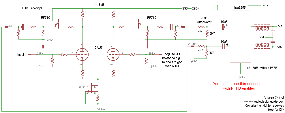
SCHEMATIC
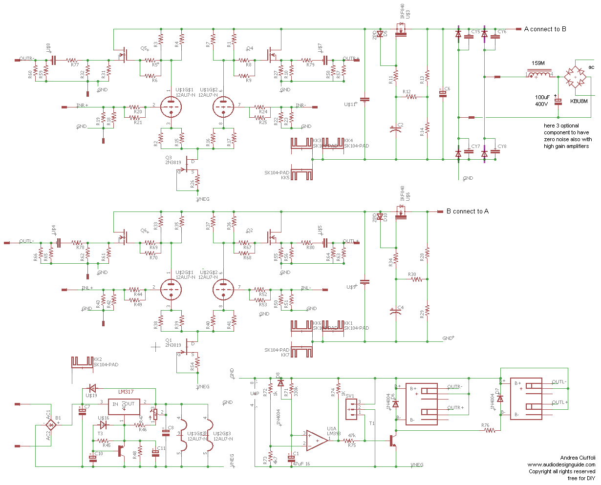
Here the schematic of the output stage excluding power supply and output relay section

This is the new complete schematic of the output stage including power supply and output relay section.
COMPONENT LIST
R1,R3,R4,R7,R33,R35,R3,R37
82K 1W 1% PR01
R2,R15,R16,R17,R38,R39,R40,R41
470 1/8W 1% RN55C4700BB14
R5,R6,R8,R9,R67.R68,R69,R70
1K 1/8W 1% RN55C1001BB14
R20,R21,R24,R25,R44,R49,R52,R53
2k 1/8W 1% RN55D2001FB14
R18,R19,R22,R23,RR42,R43,R50,R51
220K 1/8W 1% RN55D2203FB144
R57,R58,R59,R60,R65,R66,R63,R64 100K 1/8W 1% RN55D1003FB14
R10,R27,R31,R32,R61,R62,R55,R56 33K
3W 5% PR03
R13,R28
10K 2W 5% PR02
R14.R29
150K 3W 5% PR03
R12,R30
470K 1/4W
R26,R54
120-150 1/4W
R45
47K 1/4W
R48
1800 1/4W
R46 150 1/4W
R47
100 multi-turn trimmerr
R71
220K 1/4W
R72,R74
1K 1/4W
R73,R11,R34
4700 1/4W
R75
10K 1/4W
R76
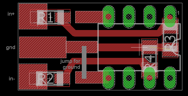
0 jumpp
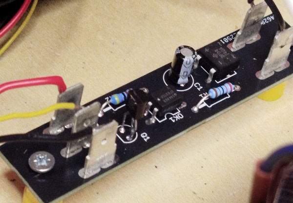
R77,R78,R79,R80
220 1/2W 1% RN60 (in series to the output capacitor, see photo)
C2,C4
33uF 400V UVY2G330MHD
C6
100uF 400V LGU2G101MELZ
C7
4700uF 25V
C1,C8,C10,C11
220uF 25V
CY5,CY6,CY7,CY8
10nF 440VAC R474I210050A1K V057
U$4,U$5,U$7,U$8,U$9,U$11
12uF 400V MKP (min. 2uF for 10Kohm load)
U43,U$6
IRF840
U$19,U$16,D6,D8
1N4007
Q1,Q3
2N3819
Q2,Q4,Q5,Q6
IRF710
T3
2N2905
U$15
LM393
B1
2KBP01
D5,D10
Zener 10V 0.5W
D1,D2,D3,D4
UF5407
U1A
LM393
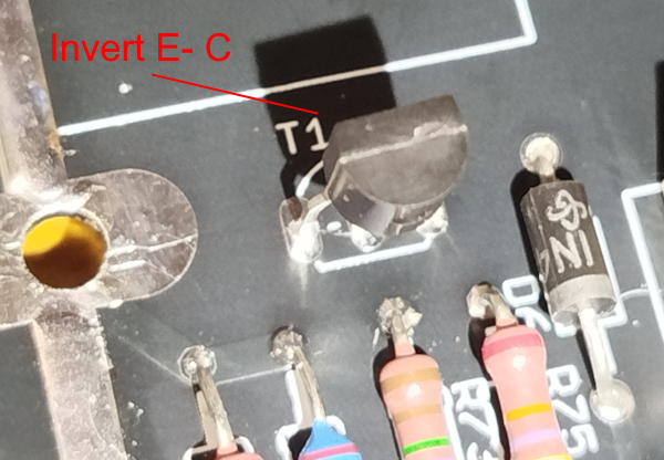
T1 BC517
(invert pin E with C)
RL1 G6S-2
2-pole micro signal relay
Connections RS 718-7987 MOUSER 571-1217056-1
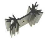 |
5 item of Heat Sink TO220 Vertical 11 Degree C/W, 2.67mm Hole, 38.1x34.92x12.7mm Aavid 513102B02500G Mouser 532-513102B25 |
You can add this circuit. to eliminate the bump on switch-off phase.
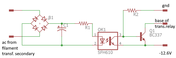
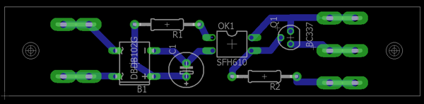
B1 diode bridge
DF02M
R1 2200ohm 1/4W
R2
4700ohm 1/4W
C1 10uF 35V
OK1 Opto isolator
SFH610
Q1
BC337
Connections
RS 718-7987 MOUSER
571-1217056-1
TRANSFORMER
In audio components the power transformer is
very important because the quality and design change the sonic result.
If
possible in my projects I use custom power trasformers with very low flux, 20%
less than normal.
In this case the primary is 260V instead of normal 220V so
all the secondaries are recalculated
primary
260VAC
instead of 230VAC
secondaries
260VAC
0.2A 52VA
15VAC
1.0A 15VA
Total 69VA
if your main is 110V the primary
will be 110 * (260 / 220) = 130VAC.
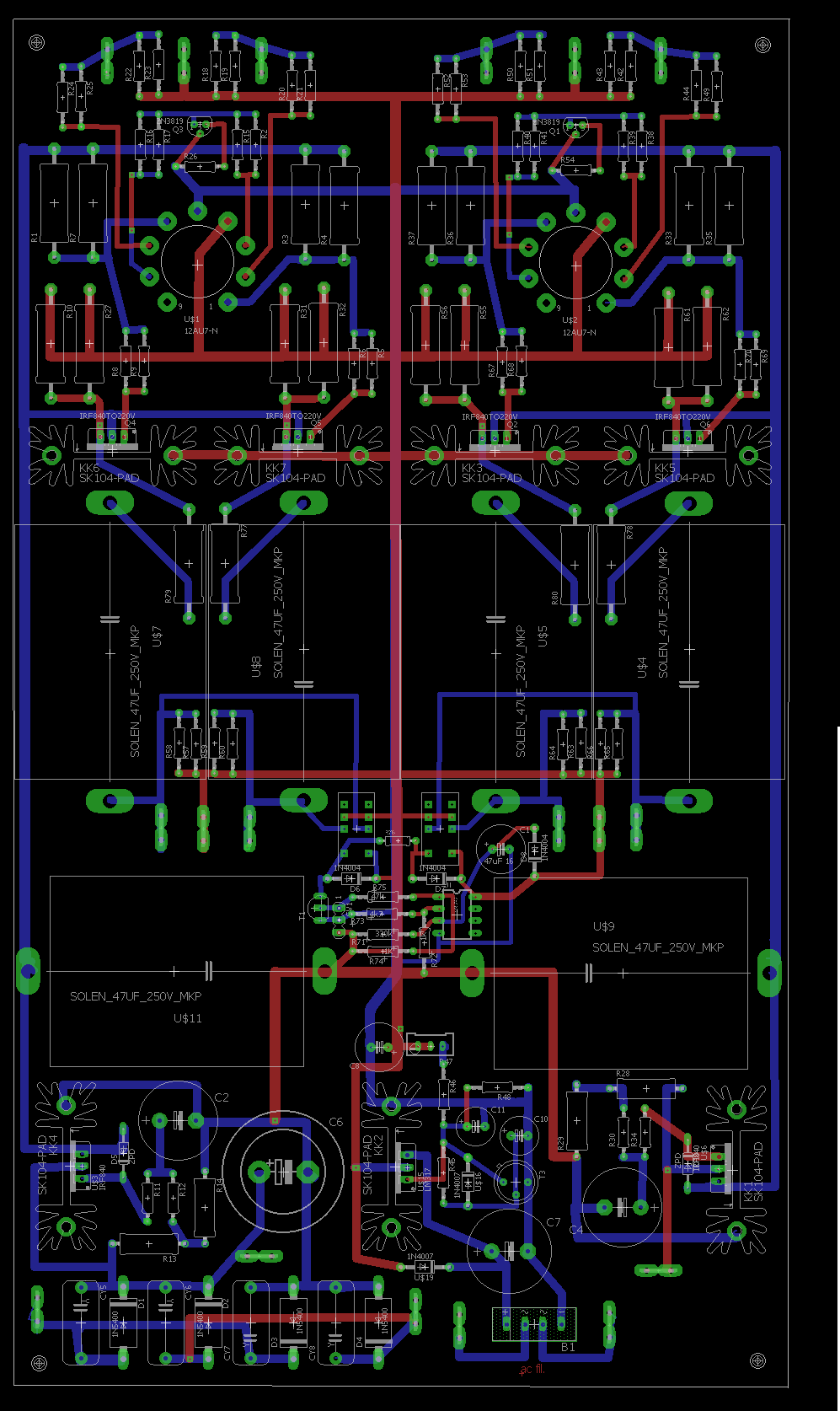
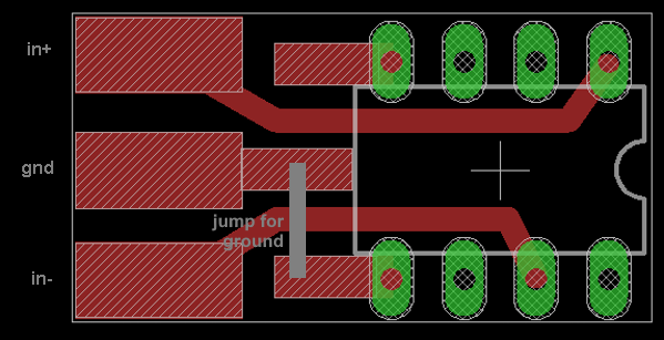
PCB
This pcb will be available on Ebay shop jims_audio.
Here the files to produce the main PCB
Here the files to produce the PCB of the soft switch-off
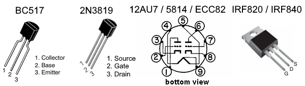
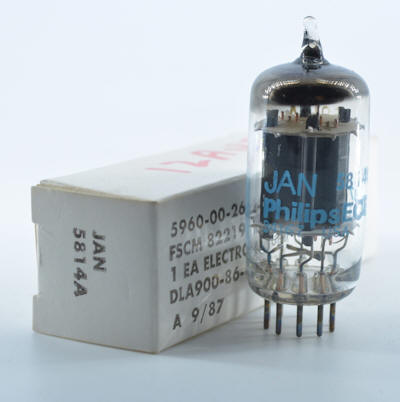
I have used a 5814 Jan Philips to get the best sound but you can use any 12AU7/ECC82/E82CC.
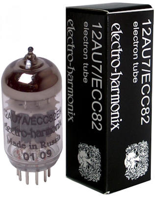
A valid alternative to NOS tubes is the EH 12AU7 which is more pleasant with some tracks.
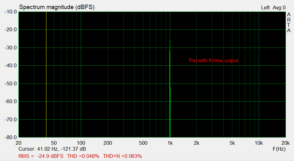
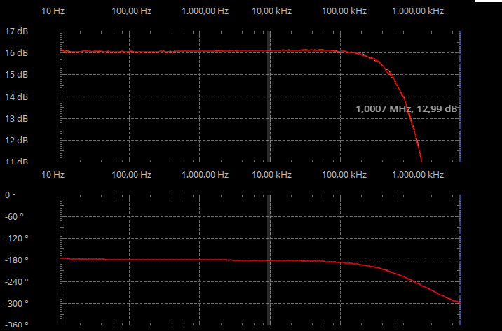
MEASUREMENTS
Output stage max distortion 0.05% at 5Vrms output and 10Kohm load.
Output stage frequency response 20Hz-20KHz at 0dB.
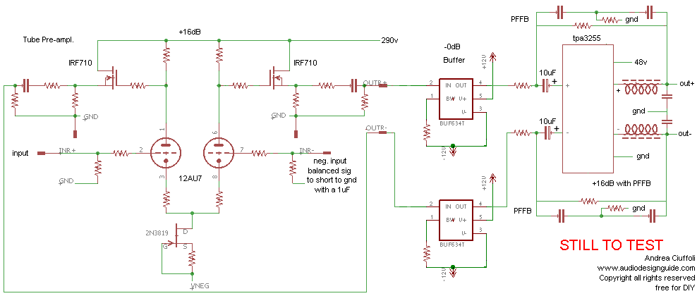
Hybrid class D system
After the good result obtain with the Hybrid Class D System, I have decided to increase the performances using a tube pre-ampl. with differential output and two dedicated class D mono amplifier modules to exclude the opamp on the signal path.
No opamp
No global feedback
No noise
Direct connection to DAC or DSC
Only 2 capacitors on the signal path
Very high slew rate
Very low distortion until 170W on 4ohm
Only one tube on the signal path
Balanced or Unbalanced input signal is accepted without modification
Very short internal wiring
Follows the simplified schematic of the Hybrid Class D system without and with the buffer to use the PFFB.
The TPA3255 is used in many modules with significant price differences starting
from $30 but only very few modules can we consider serious products for hi-end
systems.
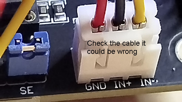
In order to integrate theTPA3255 modules with the tube preamplifier without using an opamp it is
necessary that the modules use a dual power supply for the original driver so
the decoupling capacitors are oriented in the correct direction (positive
connected to TPA input).
If PFFB
is enabled on these modules, it is necessary to add a buffer on the signal path
to keep the driver output impedance always at zero.
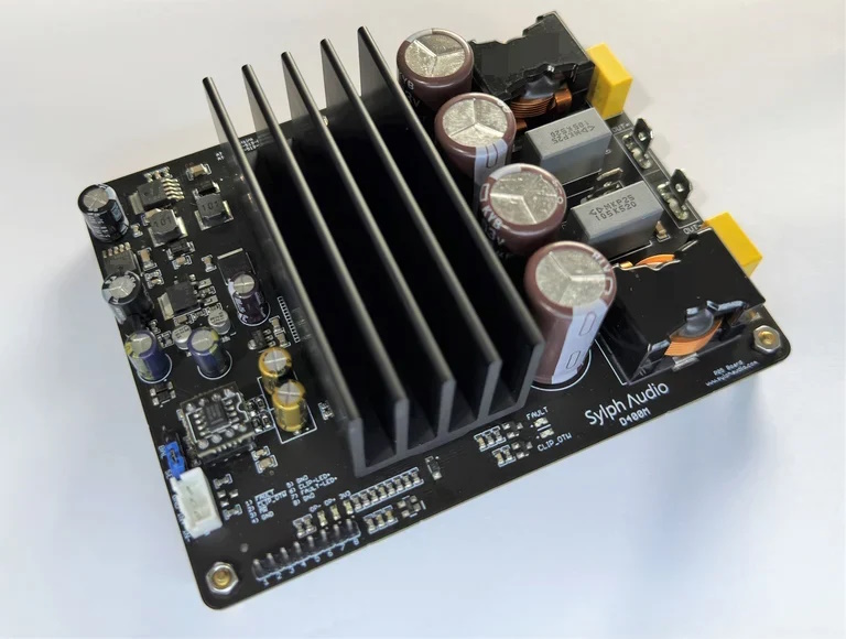
The best module I found for this project is the D400M P05 produced by Sylphaudio with these main specifications:
TPA3255 in a mono PBTL with or without PFFB
input balanced or un-balanced
opamp with split supply design so dual power supply +12V and -12V
2Ω load capability
Footprint: 130mm x 100mm x 45mm (L * W * H)
Overcurrent /short protection
Over voltage protection
Overheat protection:
Turn on-off pop suppression
The main differences from the Fosi Fox v3 are these:
the use of one chip for each channel in PBTL
the use of dual power on the driver stage
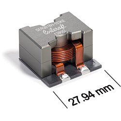
Output filter with Coilcraft SER3018H 2.56mohm instead of Sumida DEP1519 16.6mohm
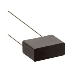
Output filter with 1uF Panasonic MKP ECWFE instead of Wima MKS 2
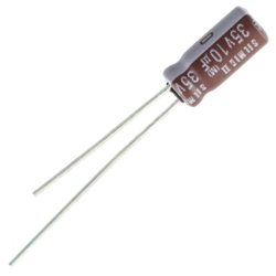
Interstage capacitor 10uF ELNA Silmic II instead of ELNA RA3
Regarding the power supply, there are numerous companies that
build switching power supplies but I chose
Meanwell products because I needed a reliable product that does not cause
problems over time.
The first tests were done with LRS-150-36 power supplies
and then I switched to the UHP-200-48 resonant
design (LLC) model with also PFC.
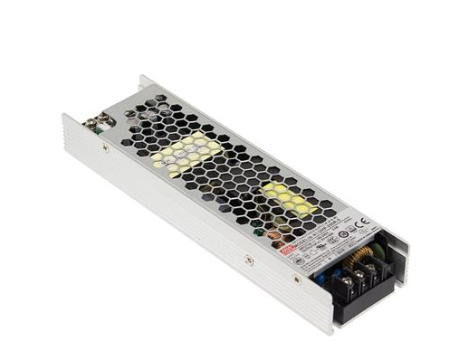
There is a huge difference in the sound by switching to the new Mean Well UHP, many harshnesses disappear and you feel a sensation of extreme cleanliness with absolute silence in the background.
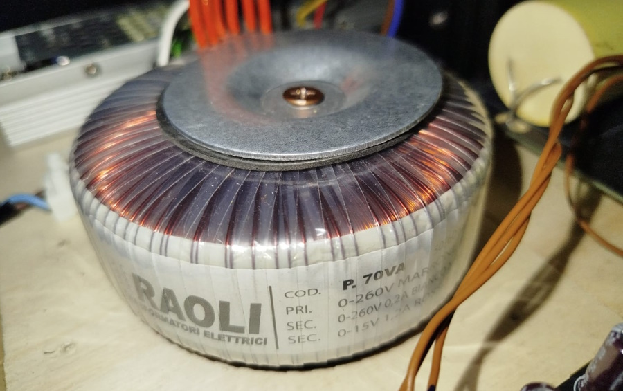
About the transformer to use for the driver section I have used
a custom toroidal on my specifications.
The primary and secondaries has been
calculated for 260V instead of normal 230V to keep the flux very low.
primary 260V
secondaries 0,2A 260V 52VA
and 1,2A 15V 18VA
total power 70W
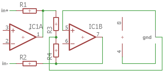
You can use this little module to connect
the tube preampl. to the opamp output of D400 (use only with TPA3255 modules
with dual power supply, ex. +12V / -12V or invert the interstage capacitors in
the correct direction).
The first version include an attenuator about -6dB to
reduce the voltage gain of the final system, to verify if it is necessary.
R1,R2,R3,R4 2700ohm
1/4W SMD 1206
IC
2 x 4 Single row connectors 2,54mm
Here the files to produce the PCB of the op-amp connection
Here the files to produce the PCB of the op-amp connection
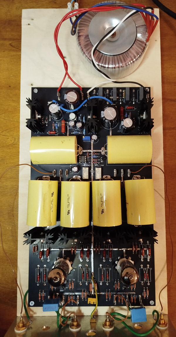
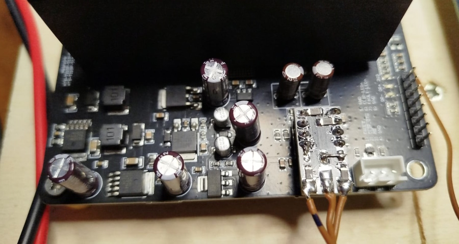
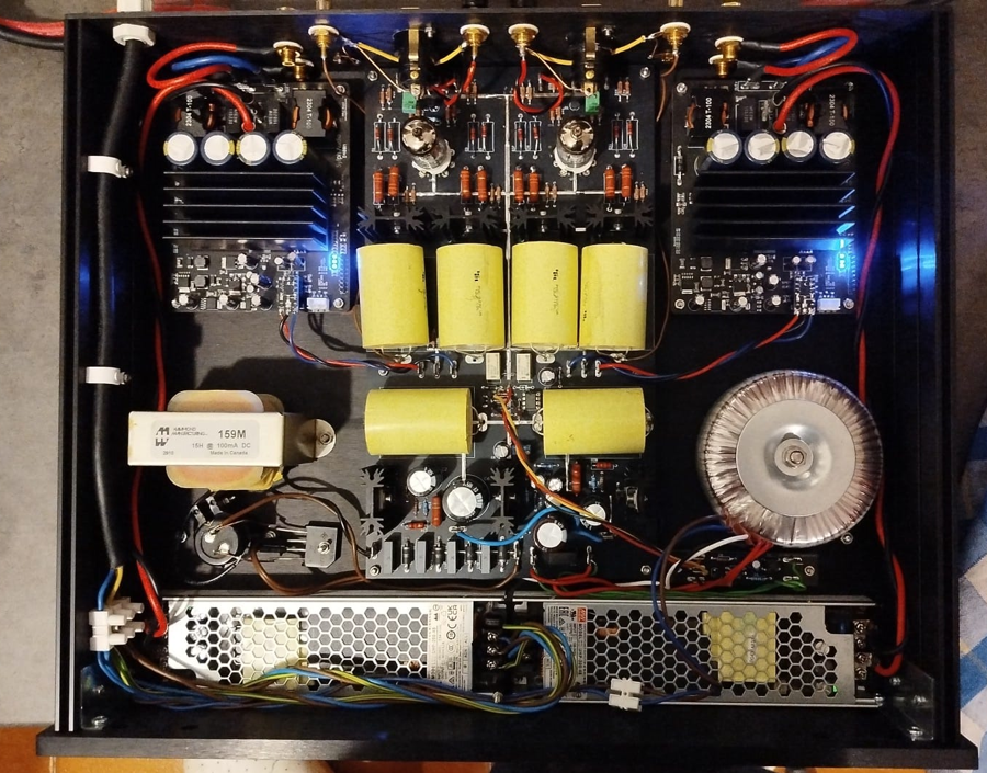
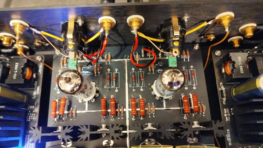
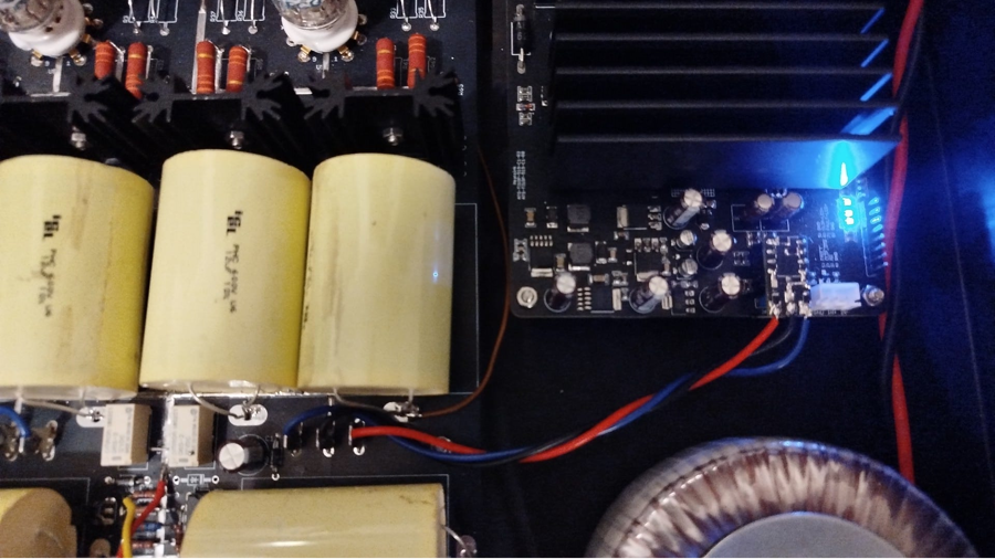
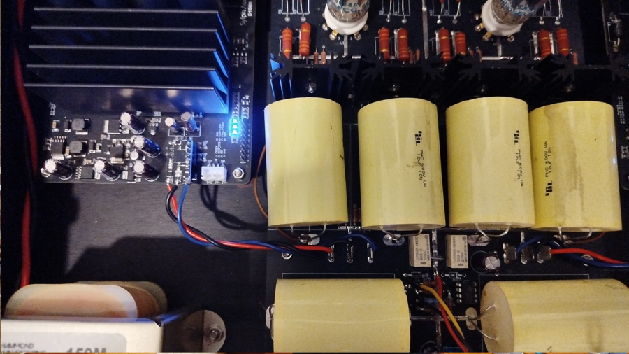
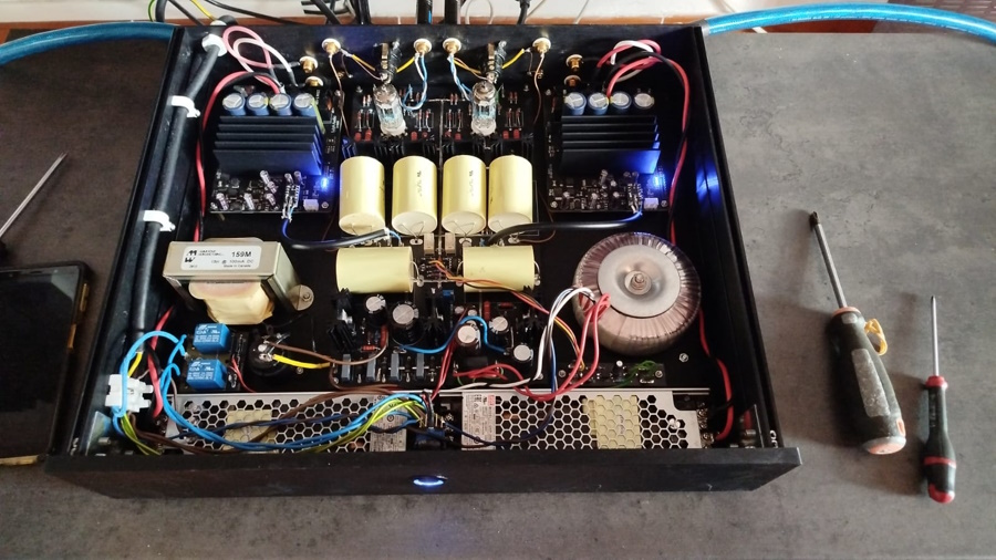
PHOTOS AND DETAILS
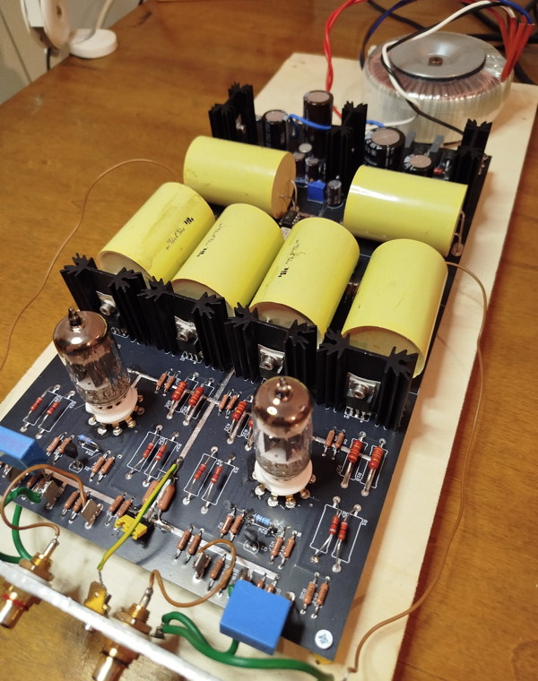
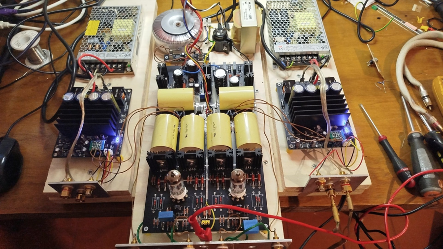
The 6 big yellow capacitors are ICEL PHC 12uF 600V 37x53mm, the same used in the my loudspeaker Monitor 2023.
You can use lower values 2uF with 10Kohm load to have an ft(-3dB) about 8Hz.
The final layout will change, here has been positioned the various component
modules for comparative tests between direct input without opamp and with opamp.
I think to rotate of 180° the D400 modules to have a very short
input and output cables.
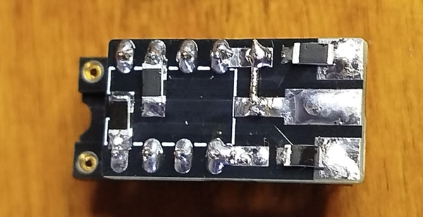 |
This is the
PCB to connect the tube preamplifier to the opamp output of on D400 module. There are 2 versions with and without the attenuator resistances. |
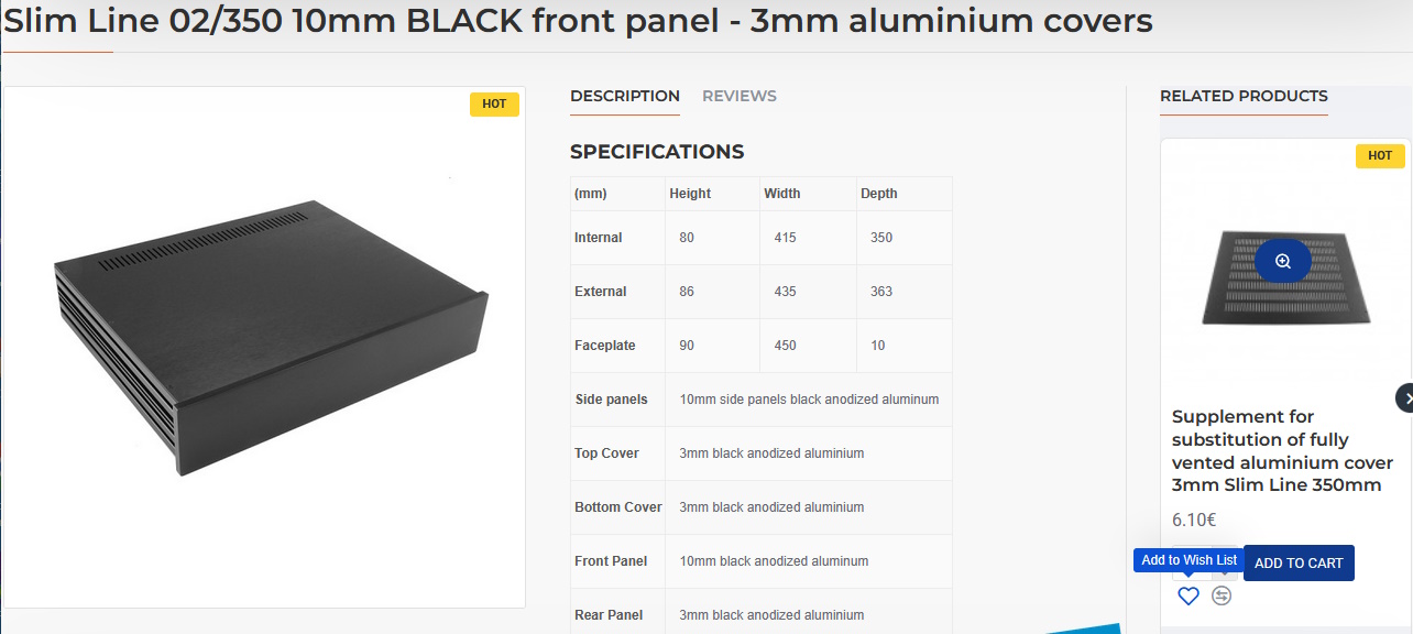
I will use this Hi-Fi2000 chassie.
Slim Line 02/350 10mm BLACK front panel - 3mm aluminium covers
Supplement for substitution of fully vented aluminium cover 3mm Slim Line 350mm
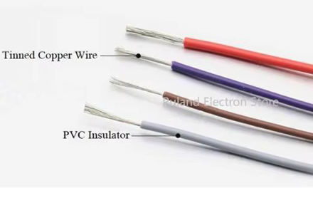
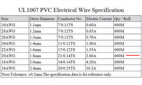
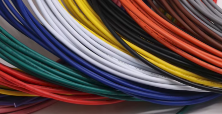
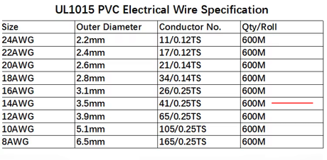
In the first time all internal cables was UL1007 and UL1015 PVC Insulation Tinned Copper wires buy on Alixpress (20AWG and 14AWG).
 |
 |
 |
 |
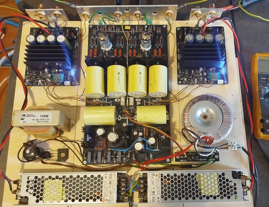
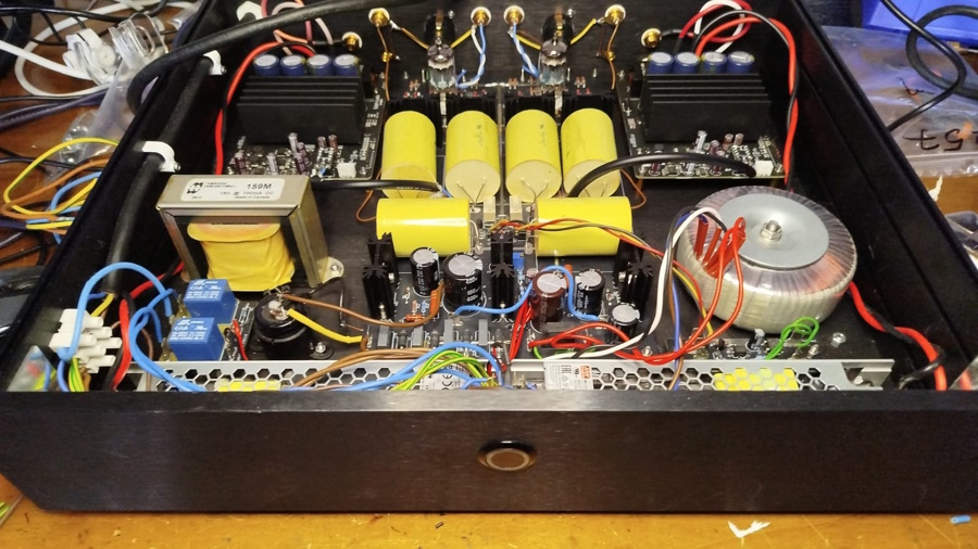
Here the internal cables has been changed with Canare L-2T2S High performance
Microphone cable shielded 0.26mm²
and 4S11G STAR QUAD Speaker cable OFC
Copper 4x2.08mm², both with with insulation PE Polyethylene.
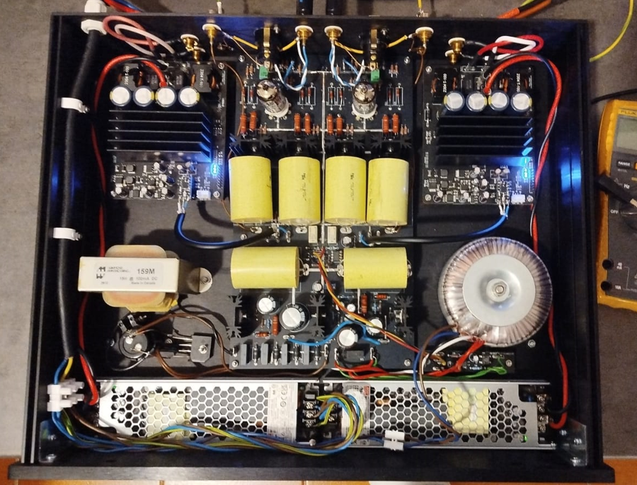
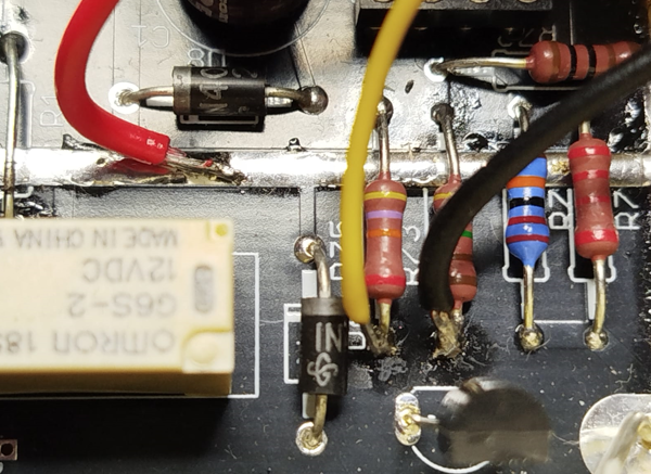
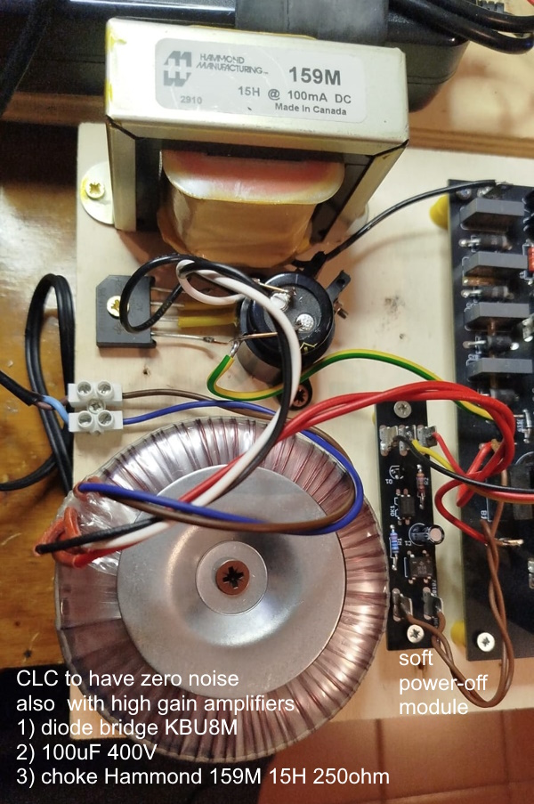
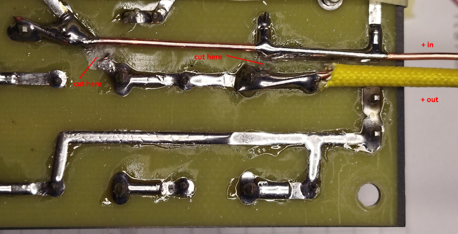
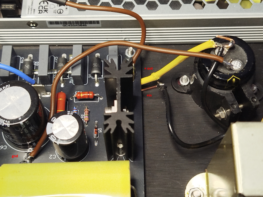
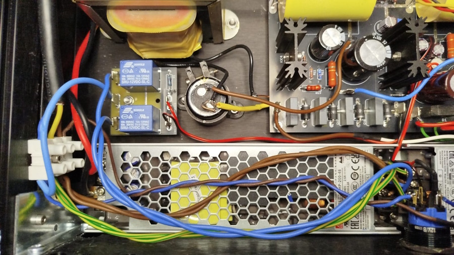
Here the last modifications to use the ultra fast diodes on board instead of the
external diodes bridge with the
CLC input filter.
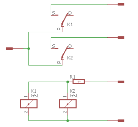
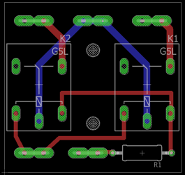
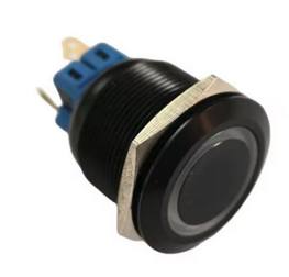
Follow the relay module to switch-on the amplifier with a low current button.
I have used a 22mm Waterproof Ring Illumination Black Anti Vandal Push Button
Switch, Blue, 1NO1NC Latching, LED voltage 12V.
 |
 |
 |
Here the file to produce this pcb.
R1 82ohm 1/4W
RLED 680ohm 1/4W in series to one pin to reduce light.
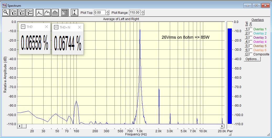
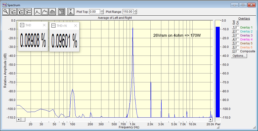
MEASUREMENTS
Below we have 2 measurements on the distortion where the exact doubling of the
power when the load is halved is evident.
In these measurements is included
the distortion of the vacuum tube pre-amplifier, so the complete system.
TOTAL COST
| description | unit price | quantity | total (euro) |
| Sylphaudio D400M P05 | 120 | 2 | 240 |
| Meanwell UHP-200-48 | 60 | 2 | 120 |
| Tube pre-ampl components (pcb,tube,cap.,...) | 160 | 1 | 160 |
| Tube pre-ampl chassie | 150 | 1 | 150 |
| Tube pre-ampl power transformer | 60 | 1 | 60 |
| total | 580730 |