
|
back
to www.audiodesignguide.com |
To get more information contact me at: webmaster@audiodesignguide.com |
The toroidal output transformer have very high performances but cannot
be used in normal
single ended design because have no gap.
Together with the Plitron OPT designer, Mr. Vanderveen, I have choiced
to use for this
project the PAT4070-CFB that have the following unusuall characteristis
for an output transformer.
| Nominal Power, RMS (note 1) | 70 Watt |
| Primary Impedance (Raa) | 4000 ohm |
| Primary Current (IDC), maximum | 258 mA |
| Sec. Load Impedance, nom. (Rls) | 5 ohm |
| Turns Ratio (Np:Ns) | 28.3:1 Ratio |
| Ultra Linear Tap | 33 % |
| Cathode Feed-back Tap | 7.1 % |
| Frequency Range, -3dB | 222 kHz |
| Power Bandwidth Start, -3dB | 14 Hz |
| Total Pri. Inductance (Lp) | 1056 H |
| Leakage Inductance, Pri to Sec (Lsp) | 3.1 mH |
| Leakage Inductance, Pri to Sec (Lsp) | 3.1 mH |
| Effective Primary Capacitance (Cip) | 358 pF |
| Total Primary Resistance (Rip) | 120 ohm |
| Total Secondary Resistance (Ris) | 0.15 ohm |
| Insertion Loss (Ilos) | 0.25 dB |
| Quality Factor (Lp/Lsp) | 338,000 Factor |
| Case size, diameter x height | 152.4 x 88.9 mm |
| Weight | 5.62 kg |
This transformer also allow several output stage configurations including
the ultralinear
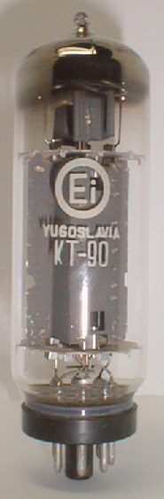
Follows some KT90s Ei items:
and the cathode feedback.
These two configurations add a little local feedback loop in the output
stage and this can be used
to reduce distortion and output resistance of the amplifier.
The output tube to get very good sonic performances and max power with
this transformer is the KT90.
The KT90 is the higher power pentode designed for audio and it has
been produced by Ei.
Ei tubes are made in the former Yugoslavia to the Philips license,
using original Philips machinery,
drawings and test procedures.
This tubes can be find at good price by
Korato
(Beograd, Yugoslavia).

This is the first circuit idea.
We have a Single Ended amplifier using a push-pull transformer and the
current mirror
balance the bias current on the transformer.
The transistor on the rigth must dissipate the same power of the tube
(about 45watt)
so is necessary to use a heatsink with high aspect ratio.
The main vantage here is the low cost and ofcourse a triode could be
used instead
the pentode in triode connection as show.
Here the transistors could be low power as BD139 and the second tube
could be driven to switch in push-pull from single ended when we need
more power.
The current mirror balance always the bias current on the transformer.
We can also set the input of tubes to get the same distortion spectrum
of
a single ended but more power
This configuration should run very well in class A when both the grids
are driven but when
we drive also one grid to get the best sound of single ended the tube
with no signal on grid
will function as a load for the other.
To skip this problem I suggest to use a triode to pentode switch as
this following schematic:
Here there is the Pure Single Ended design and a direct heating tube is used.

If we want use this design in Single Ended mode only, ofcourse we can
change the first penrtode with
a triode and the best triodes are the direct heating types.
The direct heating output triodes are the best because are more linear
of any inderect hating output tube.
Searching a direct heating triode that can be used with Plitron output
transformers 4070-CFB, with a
primary impedance of 2000ohm (4000ohm anode to anode) I have
found two KR Enterprice tubes:
the KR300BXLS and the KR52BX.
In order to achieve the following points, this project include a digital input circuit.

As you can see in the input stage schematic for the Push-Pull/Single Ended there are two controls:

The disadvantage of this design is the redution to half of the signal in the push-pull mode (center position of switch) so to get the max output power from the amplifier the voltage stage should have a double gain.
See here the simulated distortion spectrum of output stage in three
different modes:

As is visible on input stage schematic for Push-Pull/Single Ended I
unsing the Evaluation Board CDB4390 from Crystal Semiconductor to have
a pre-assemblated solution.
Of the CDB4390 the output stage wth op-amp. is not used.


This power supply has been designed to reduce current peaks on diodes
of bridge that create problems for sonic performances.
So, the first capacitor connected on bridge have a little value, only
220uF, and the larger capacitor is only after the stabilizer chip.
The 1N4007 diode protect the 7805 chip from reverve current in switch
off pahse.
An improvement to this power supply is possible using an LC cell
on output.
Follows the layout of power amplifier section

and here the section

Follows the layout of DAC section
