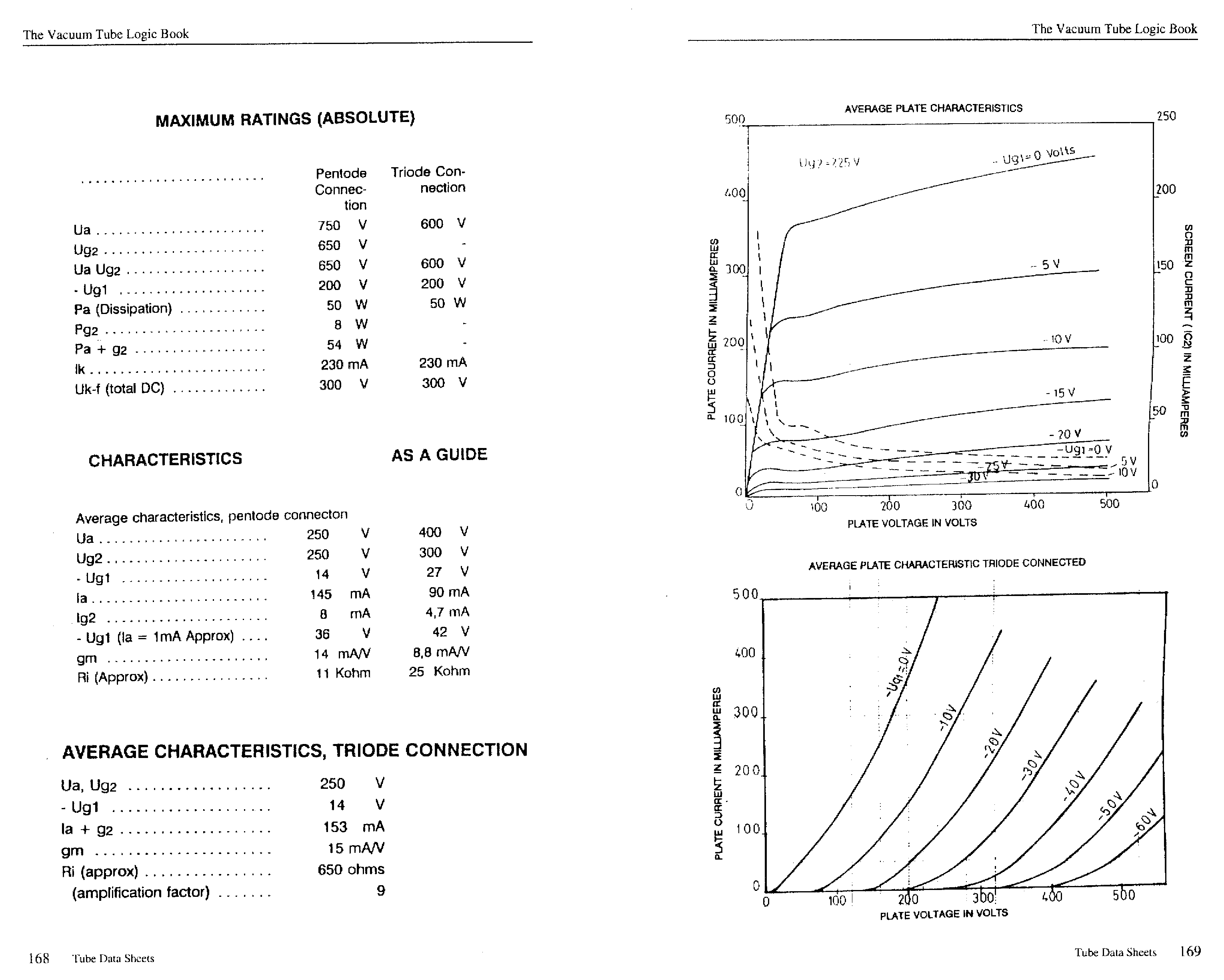
|
back
to www.audiodesignguide.com |
To get more information contact me at: webmaster@audiodesignguide.com |
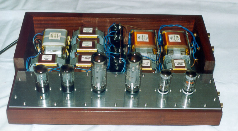
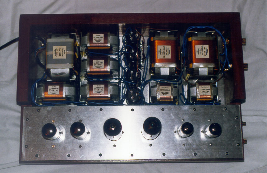
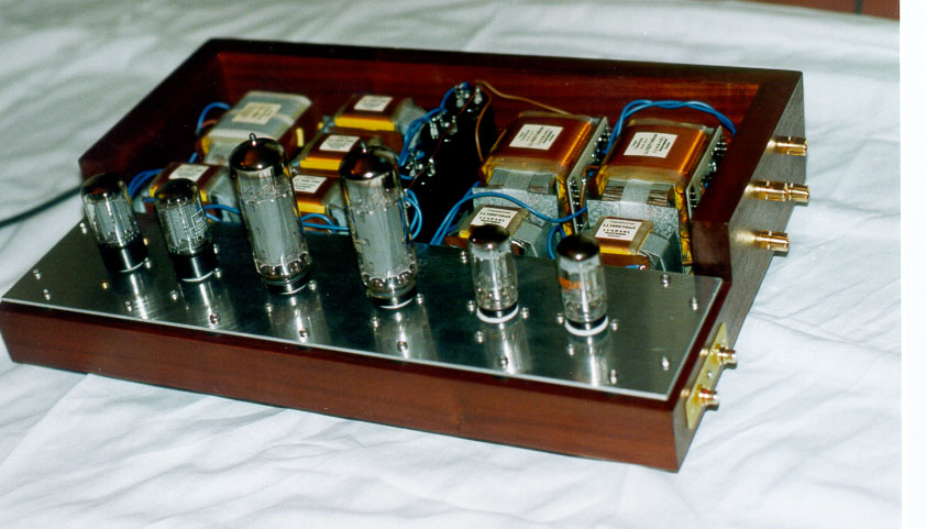
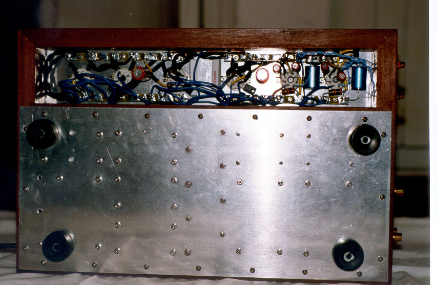
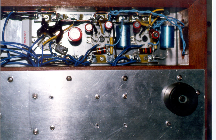
Here some photos
Such a topology is pretty difficult to implement, due to a severe input
voltage swing request (over the power tube
grid). Such a large voltage can be obtained by the means of different
solutions:
Since a low damping factor is very difficult to achieve with a vacuum
state amplifier, it is often kept rather hidden,
nevertheless its bad impact over any loudspeaker system, especially
for those with a complex impedance figure or
significant phase rotation over the frequency spectrum.
As output tube I am using a power pentode in triode connection instead of a direct heating power triode because the cathode follower configuration add itself a local feedback that increase the linearity of the output stage and is preserved the sonic characteristic of driver stage.
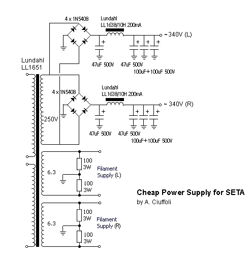
This project use a reference design vacuum tube power supply rectifier
with choke input.
The main vantage of choke input rectifier is to skip any current peak
generation on rectifier diodes that are present in normal capacitor input
design.
The filaments are in AC and I have choice this type instead the DC because
the normal DC power supply design with large capacitors generate very high
current peak about 50A and the spectrum noise is amplified (the gain in
this case 250V/6.3V = 40x so about 32dB) and go on high voltage secondary
given terrible effect on sound.
The main results should match these items:
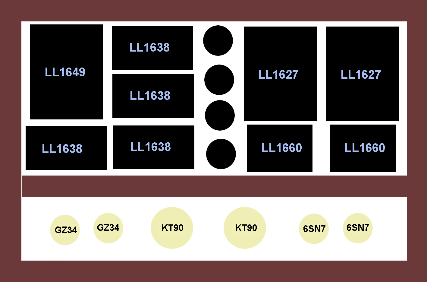
All the transformers used in this project are
Lundahl products:I have used the Lundahl transformers also in my new
transformer coupled headphone amplifier and in the DAC getting in both case incredible performances.The total price of the transformers is 811$ or 616$ for the cheaper
version without vacuum state power supply and with only one inductance.
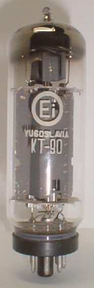
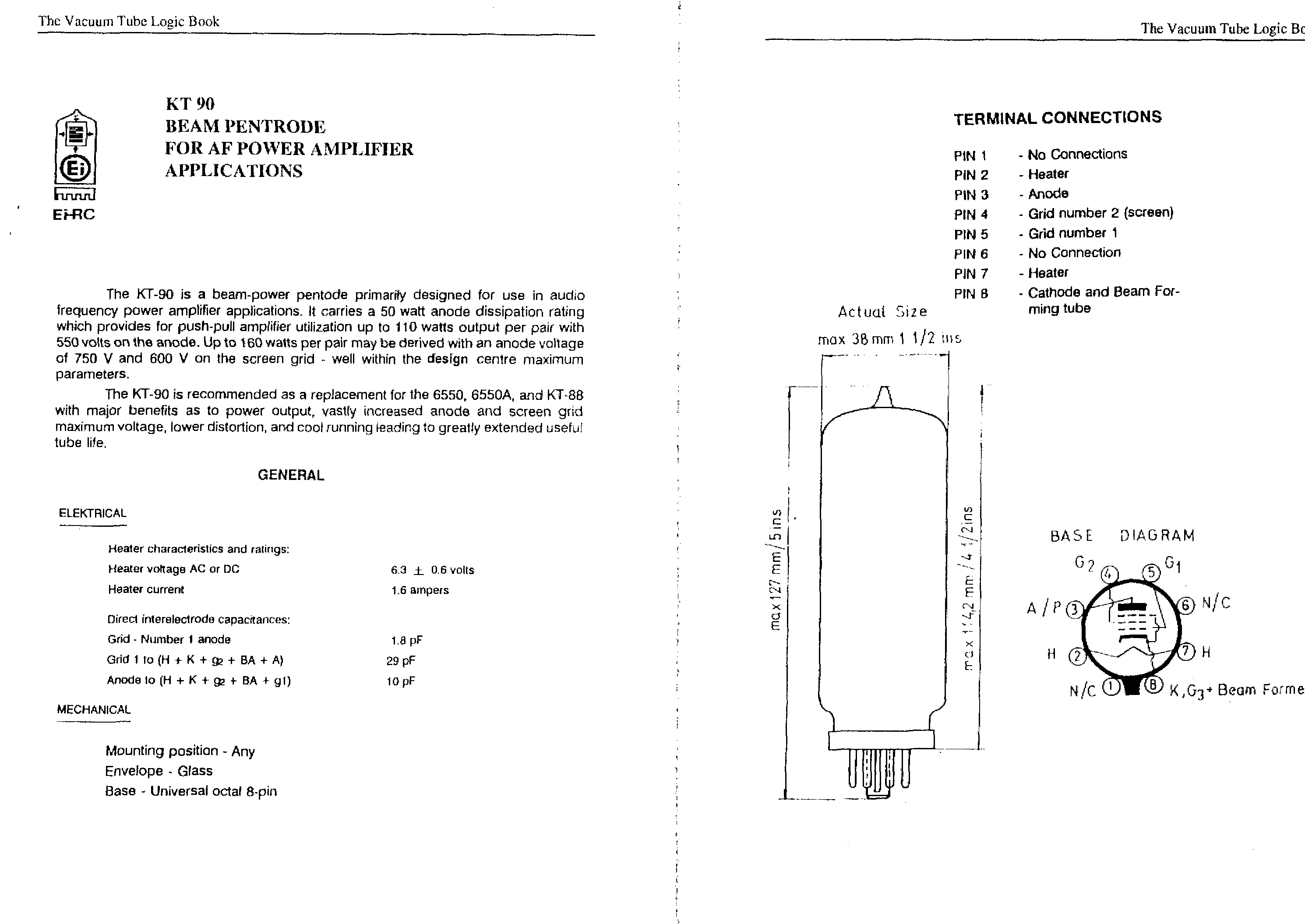
The output tubes to get very good sonic performances and max power in this project are the KT90.
The KT90 is the higher power pentode designed for audio and it has been
produced by Ei.
Ei tubes are made in the former Yugoslavia to the Philips license,
using original Philips machinery, drawings and test procedures.
These tubes can be find at good price by
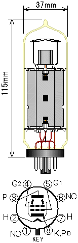
Follows some KT90s Ei items:
I have tested also the KT88 Teslovak (considered with high sonic performances), the new KT88 Svetlana and the new 6550WE Sovtek.The better alternative to the KT90 is the KT88 Svetlana
The tube diode rectifier GZ34 should be the Mullard version. Some DIY
don't like the sound of the GZ34 because consider this to much hard near
solid state diodes but this is not true because depend by the power supply
design and with inductive power supply we will have the best result.
About passive components types, I don't leave many choices: Allen
Bradley resistors on anode, Holco or Caddock resistances on cathode, ELNA
Cerafine capacitors on cathode and power supply.
About wire forget the teflon ! use only stranded tinned copper wire
with pvc isulator and for loudspeakers I am testing the elevator cables
(paralled wire with a good section).
About the 6SN7 I have tested, togheter with my friend Francesco
Pintavalle, many types and to get the best sonic performances the 6SN7
Jan Philips is the first choice.
For all my new projects, I am using the very good ELNA Cerafine capacitors
that I love and which can be find at good price by
The ELNA Cerafine capacitors contain super fine ceramic particles which,
through chemical reaction, improve the discharging speed between the anode
and electrolyte with very low distortion.
Any other electrolytic or polypropylene capacitor give very lower sonic
performances introducing some alteration. Only the Blackgate WKZ could
give better sound, but I have not tested it and I know of some problems
during startup phase.
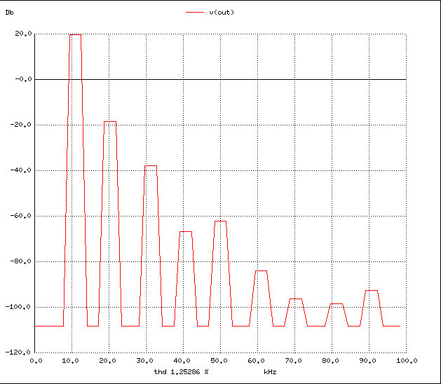
The projects below have been simulated with spice release 3f4 running
over a UNIX in order to optimize their performances. The spice3f4
tube models have been computed by a complex function, with a custom program
working on the real plot for the output characteristics (Ip vs Vp @Vg)
for any of the tubes he is interested in.
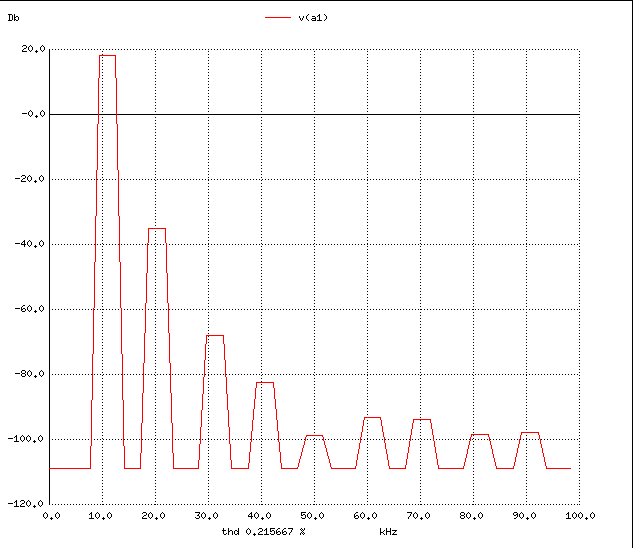
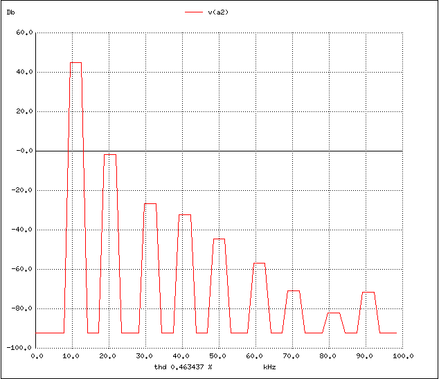
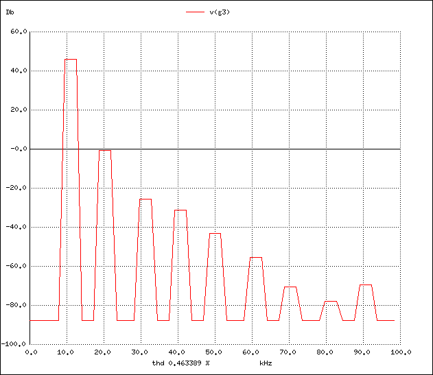
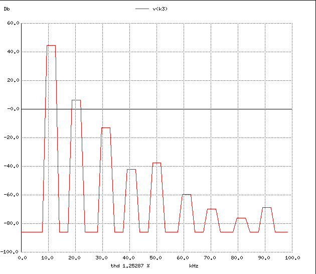
The distortion spectrum below has been plot by Spice3f4 using a my custom command "plotfour" add to the original
Berkeley's programs.The Spice3f4 sources are available for donwload at
ftp://ic.berkeley.edu/pub/Spice3/ and can be compilated on many Unix operation system (on PC use Linux).A nice porting on Windows could be find at
S. C. Wong's Home Page.Here some simulation plot results at the max power:
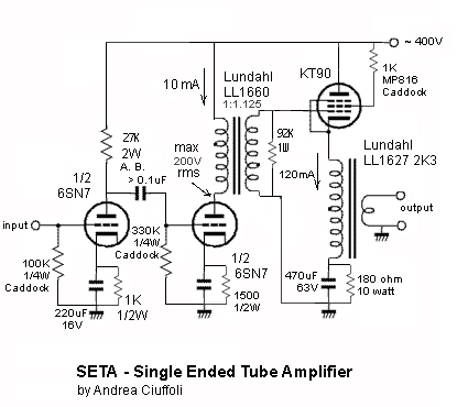
We have a first simple voltage stage with one section of the 6SN7 coupled
by a capacitor, the uinque interstage capacitor of this amplifier, to next
stage.
The voltage gain of this first stage is about 17x (22dB) and little
chaneg of the anodic resistance should be done to optimize the sound and
gain from 27K to 39K.
The second stage is loaded by .......
The cathode resistance of output stage should be 150ohm (about 46watt 140mA) or 180ohm (about 36watt 120mA) using the KT90 and 220ohm using the KT88 (about 36watt 120mA).

The Hybrid Graetz Bridge concept after a Fulvio Chiappetta paper, published
by the Italian Magazine 'Costruire HiFi' a reference for the DIYers.
He tested and comparated this topology versus a pure tube vacuum state
power supply design with a 300B output tube amplifier and there was no
difference both while listening and measuring the output noise spectrum.
I built this power supply and the sonic result is very high even if it uses semiconductors the sound depends on the rectifier tube.
Infact the vacuum tube rectifier is in series with the solid state diode and the switch characterictic is of the lower speed device so the tube.
The 0.27 ohm resistors could be adjusted to have correct 5V on filaments of tubes and a value range from 0.18 ohm to 0.33 ohm should be good to test and match any rectifier.
To reduce a little the cost of this project without compromise the result is possible to use only one tube rectifier per both channel but the two secondary 11-13 and 12-14of the transformer must be paralleled to balance flux.
Another little reduction can be obtain using a unique LL1638/8H 250mA inductance instead the two LL1638/10H 200mA that follow the rectifier bridge.
This must be considered as the last solution when cost and size are very important or as a starting point to test this amplifier.
Here the same power supply transformer of the reference version is used but in this configuration the high voltage secondaries are in parallel to get 250V instead 500V.
To reduce more the cost also one bridge and one inductance LL1638/8H 25mA could be used per both channels, instead two LL1638/10H 200mA, but the separation will be compromized.
I am currently finishing up the final adjustments for the driver stage
bias/load line. The amplifier has been tested with different output tubes
and supply configurations, by two listeners (Andrea Ciuffoli and Francesco
Pintavalle)
The overall sonic result is excellent : werll balanced and very natural.
Lower end does not resemble a tube amp so much, it is clear and tight,
deep and defined. Effects of the good damping factor.
It is of interest the sonic influence of the supply tubes, where the usage of a 5R4 RCA gives impressive results in particular for the firmly focused soundstage.
The KT90 since to be the better choice for output power but the KT88 Teslovak and the new product KT88 Svetlana used with the 5R4 RCA vacuum diodes (instead the GZ34 Mullard) given a more hot sound near to direct heating tubes like 300B.
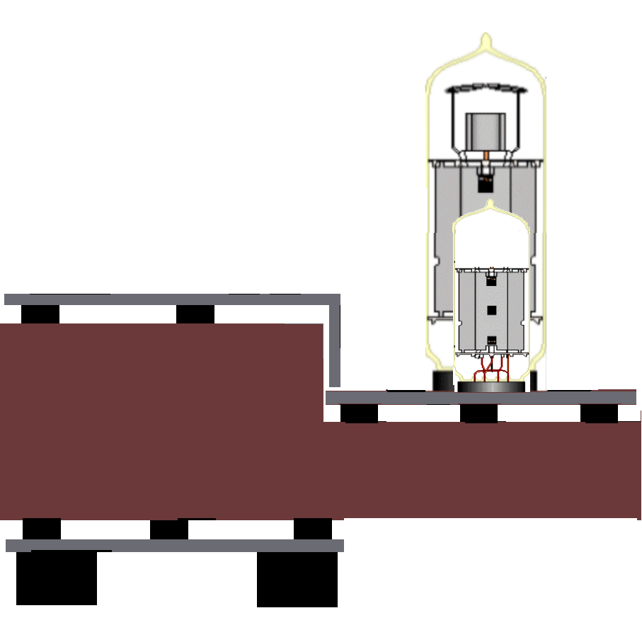
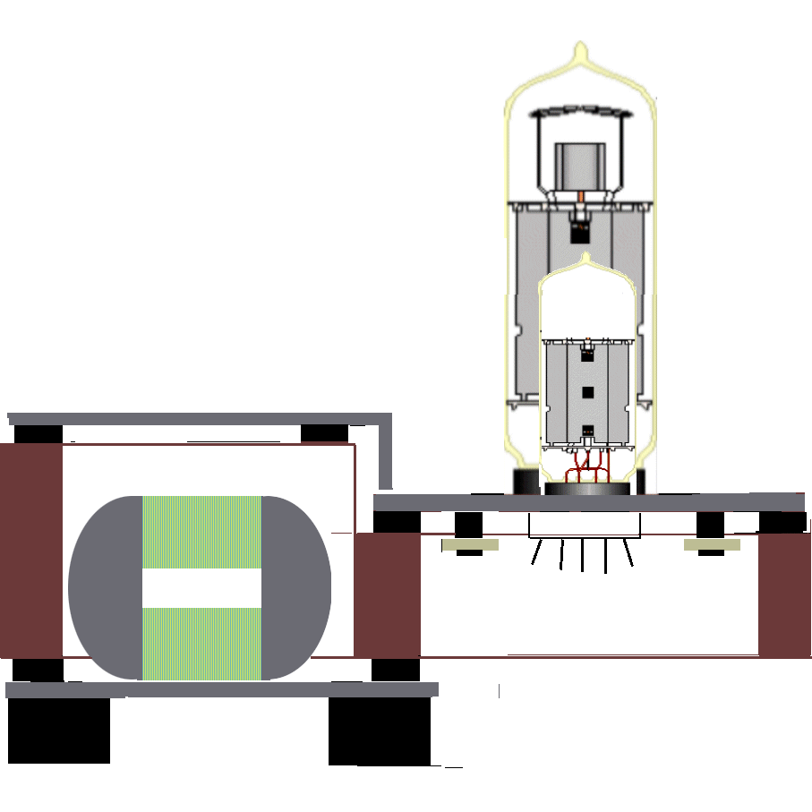
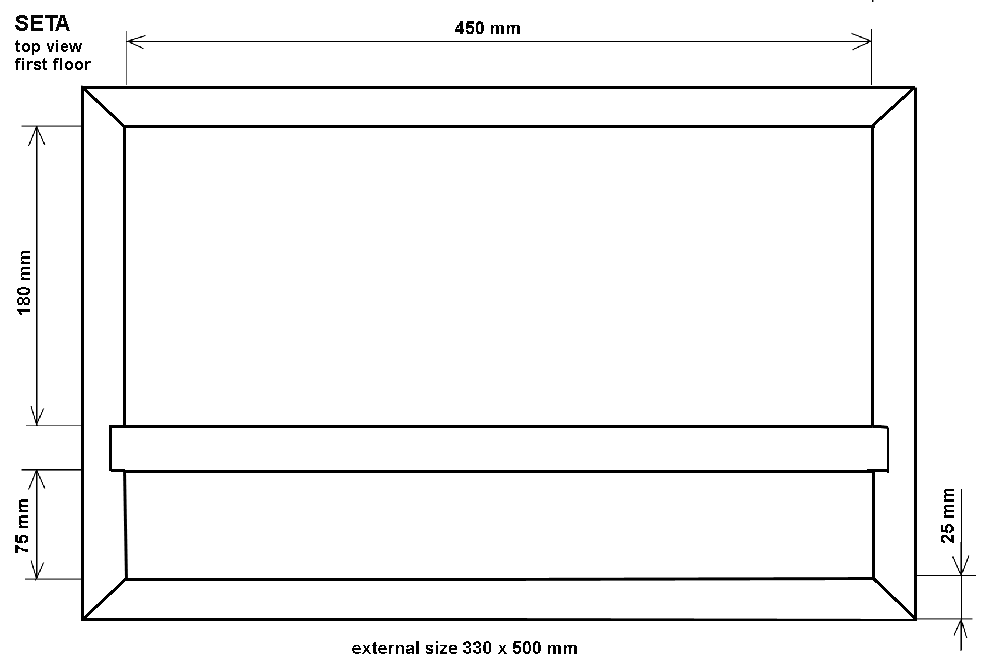
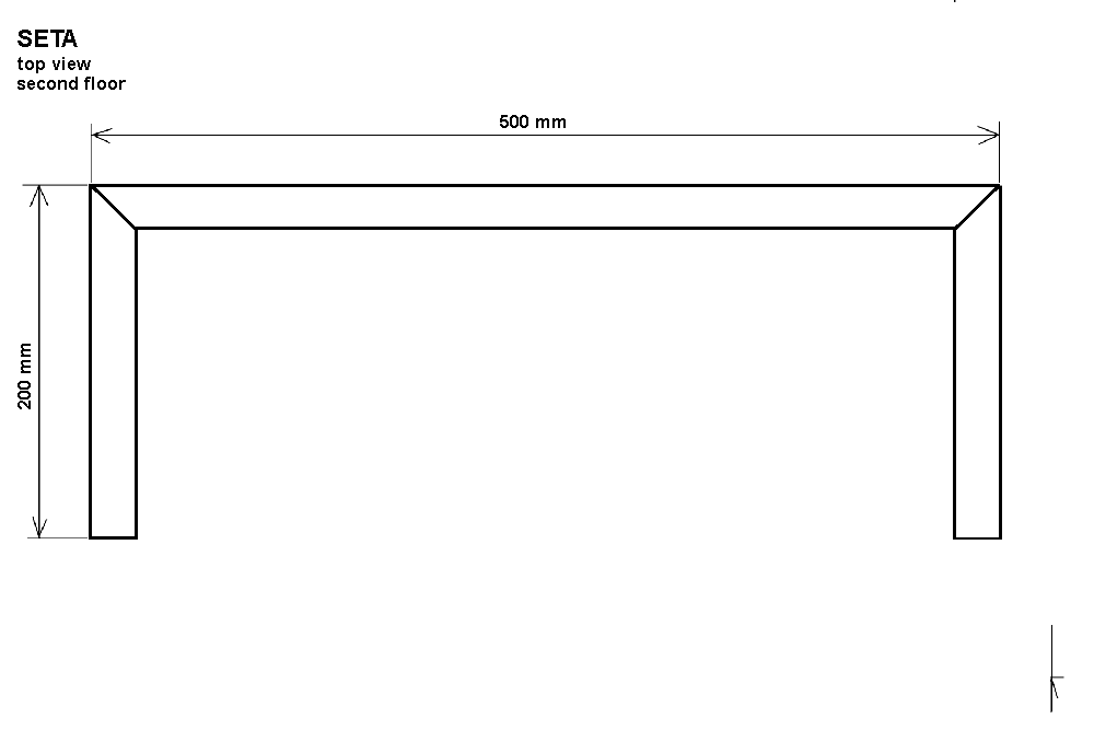
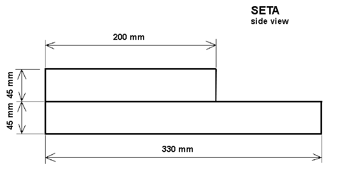
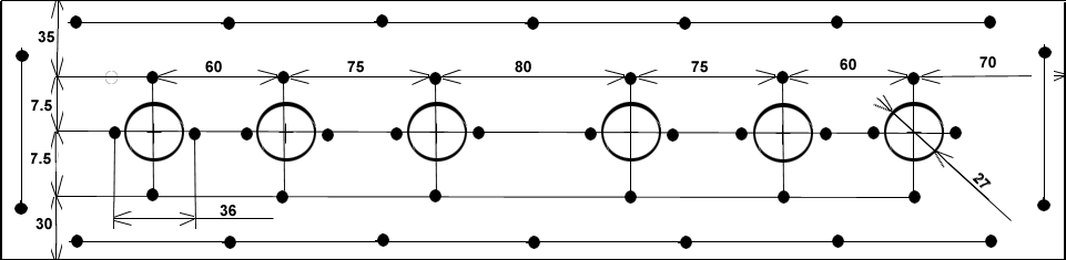
click on the images to get real scale
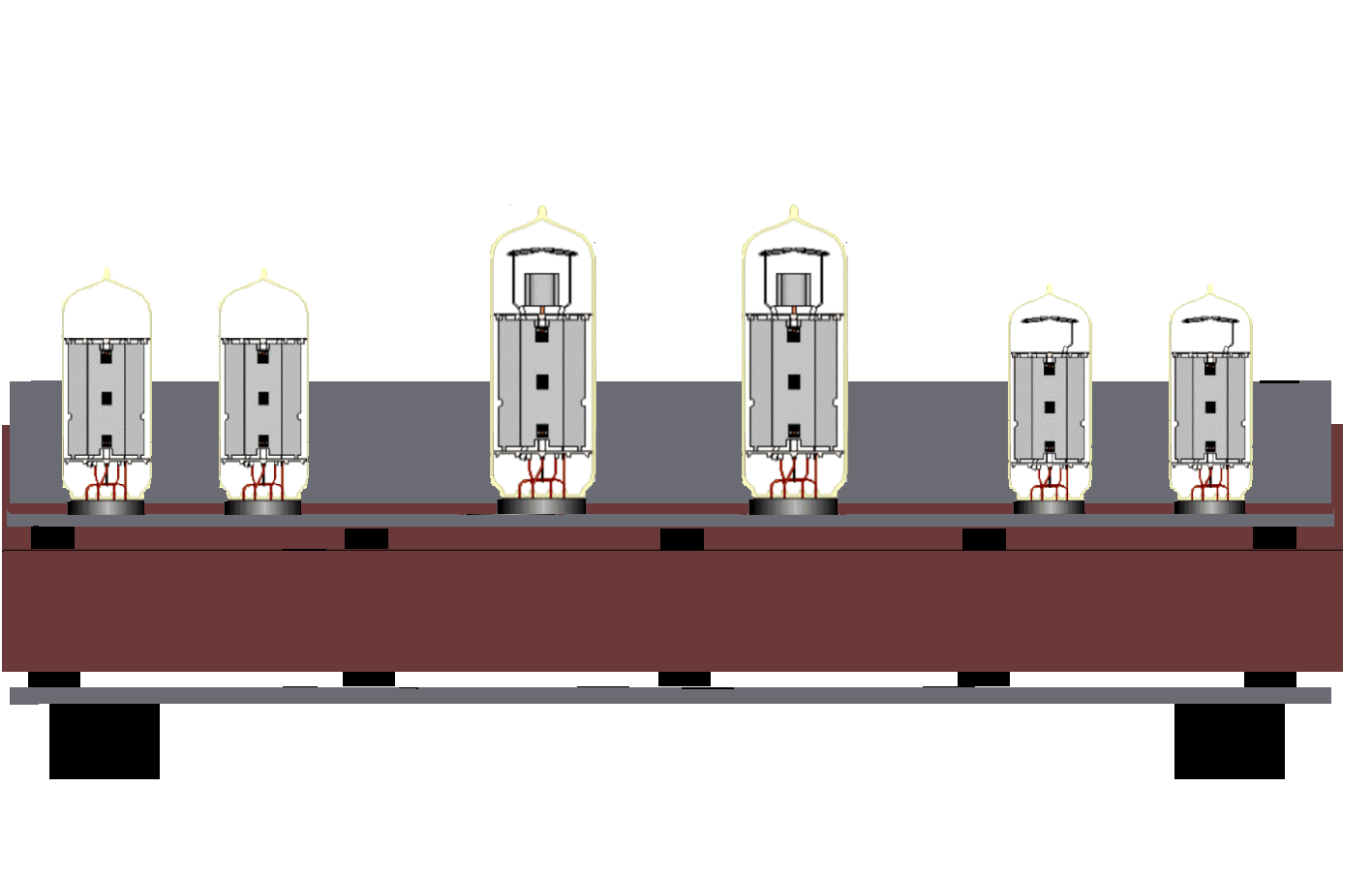
Attention:
some 100uF+100uF 500V ELNA Cerafine capacitors are higher so you should
use an higher chassie!
click on the images to get real scale
3 mm aluminium with external size 490 x 220 mm
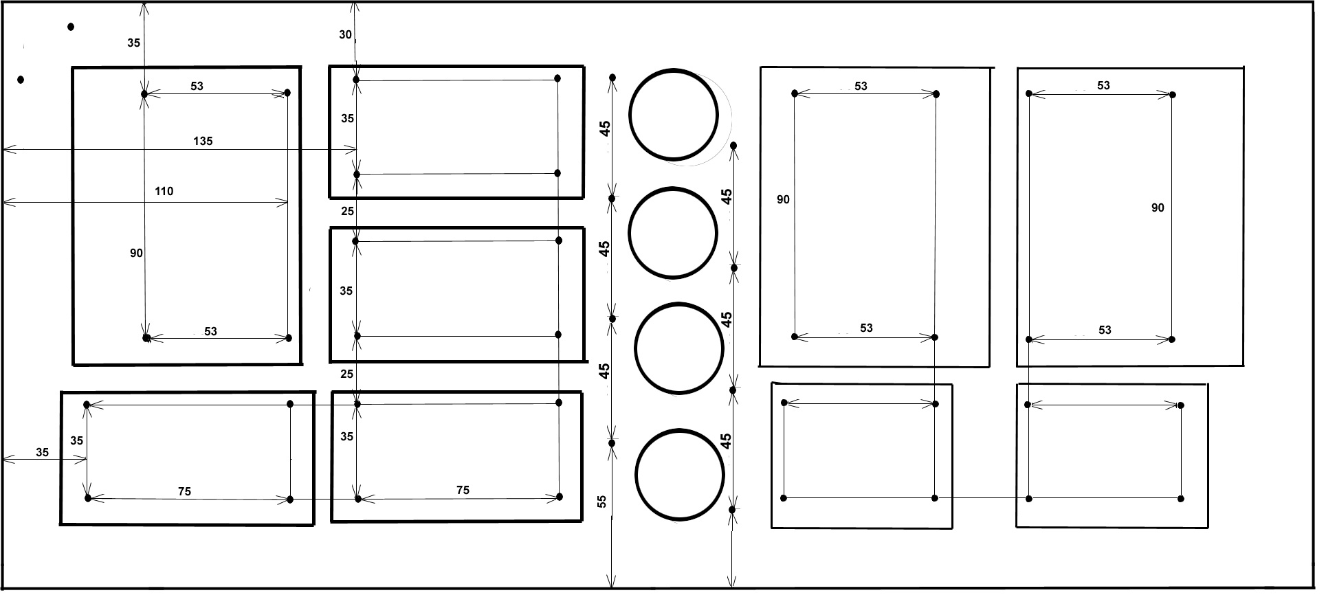
3 mm aluminium with external size 490 x 120 mm