the 300BXLS Single Ended Amplifier
by Andrea Ciuffoli - LAST UPDATE 18 Oct 2001
| ATTENTION: |
this project is in design phase
so any part could change in the near future. |
Introduction
This project is created to integrate in a single component all the experiences
made on the previous projects.
Here no compromise has been accepted in any stage.
The main results and targets should match these items:
-
top sonic performances
-
2 stages only from DAC chip to the loudspeakers
-
very low distortion
-
good damping factor with an output resistance near 1.5ohm
-
very good low frequency response about 10Hz (-3db)
-
no electrolitycs on the power supply but only paper in oil
-
no voltage duplicator on the power supply
-
soft power supply using indirect heating vacuum diodes (6D22S Svetlana
or GZ34)
Components
 |
The KR300BXLS is an ultra-linear, low
frequency, high power triode tube capable of producing 15-25 watts of pure
class-A power. The KR300BXLS may be used in 300B amplifiers, however
you will still obtain only 8 watts. Therefore we recommend the KR300B
for these applications. However, if your amplifier has adjustable
bias, the KR300BXLS will provide more power. Increasing the plate
voltage and current will result in higher power than is obtainable with
other 300Bs. Consult your equipment manufacturer before increasing
the power of your amplifier.
The KR300BXLS features a new ribbon filament construction and the KR
Electronics exclusive patent design with 32 cathodes.
As with all KR Electronics vacuum tubes, the KR300BXLS possesses a vacuum
of 10-8 Torr, a maximum grid current of 2.0 microampere and absolutely
constant emission over the life of the tube.
All KR Electronics vacuum tubes are warranted for a period of 2 years.
Information from:
|
All the audio transformers used in this project are
Lundahl
products and the distributor list is available
here

Lundahl is one of the world´s
leading manufacturer of audio transformers used in many professional studio
recording and radio stations so it has great experience and all these products
use a custom audio C-core.
I am using a
DACT stepper attenuator
instead of the normal ALPS or NOBLE solution, because the the sound is
clearer. A good review of these components can be found on the
article
published in Hi-Fi World.
The input stage is the very good Golden Dragon 6SL7.
The vacuum diodes used are the 6D22S Svetlana to use with the PC509 connector.
About passive components types, I don't leave many choices:
Caddock resistances on cathode, ELNA Cerafine capacitors on cathode.
In all my previous projects I have used in the power supply the ELNA
Cerafine capacitors with a very high sonic performances and compact size.
If we skip any economic aspect and if there are no size problems the
first component is a paper in oil capacitor.
In comparation test the paper in oil are best of the ELNA Cerafine
or other electrolityc type.
It is important to find new products such as Jensen and not old stock.
About wire; forget the teflon ! Use only stranded tinned copper wire
with pvc insulator, and for loudspeakers use the same.
A very good quality stranded tinned copper wire could be bought directly
from E-Z-HOOK that carries an extensive
line
of fine stranded and extra flexible wire.
Design
As in all my amplifier projects my first point is get a very good damping
factor to have good bass frequency and good control of loudspeakers.
To get good damping is necessary to use upper impedance of the output
transformer but this ofcourse reduces the output power.
In this project for the 300BXLS I have used a 5600ohm on 8ohm that
mean a turn ratio of sqrt(5600/8) = 26.45 instead of the suggested
2000ohm that means a turn ratio of sqrt(2000/8) = 15.8 or sqrt(2000/4)
= 22.4 depending on load (4 or 8ohm).

The first step in the design is plot the line of the maximun power dissipated
by the tube.
I have ploted the line relative to a power 10% less than max power
58.5W.
For each anode voltage has been calculated the relative current at
this power with:
P0 = Pd / Va = 58.5W/585 = 100mA
P1 = Pd / Va = 58.5W/520 = 112mA
P2 = Pd / Va = 58.5W/455 = 129mA
P3 = Pd / Va = 58.5W/390 = 150mA
P4 = Pd / Va = 58.5W/325 = 180mA
P5 = Pd / Va = 58.5W/260 = 225mA
I have choicen the operation point PA (487V and 112mA) for this first
test.
Pa = Va * Ia = 487V * 112mA = 54.8W about 55W of power dissipated on
tube
Now to draw the output line we need to calculate the end point on current
axe with:
PB = Va / Rl + Ia = 487V / 5600ohm + 112.5mA = 199mA on 8ohm
PC = Va / Rl + Ia = 487V / 2800ohm + 112.5mA = 286mA on 4ohm
click on the image to enlarge.

You can calculate the output power for the two power supply voltage
on 4-8ohm load with:
1) (406 - 142) / sqrt(5600 / 8) = 264V / 26.45 = 10Vp = 7.1Vrms
=> 6.3W on 8ohm in pure class A1 operation
2) (406 - 170) / sqrt(5600 / 8) = 236V / 26.45 = 8.9Vp = 6.3Vrms
=> 10W on 4ohm in pure class A1 operation
3) (503 - 150) / sqrt(5600 / 8) = 353V / 26.45 = 13.35Vp = 9.46Vrms
=> 11.2W on 8ohm in pure class A1 operation
4) (503 - 170) / sqrt(5600 / 8) = 333V / 26.45 = 12.6Vp = 9Vrms
=> 20W on 4ohm in pure class A1 operation
And the bias current for each of previous points with:
Ia(min) = 1.41 * sqrt(Pout/Rload)/(turn ratio) = 1.41 * sqrt(Pout/Rload)/sqrt(5600/8)
= 1.41 * sqrt(Pout/Rload)/26.45
1) Ia(min) = 1.14 * sqrt(6.3W/8ohm)/26.45 = 47mA
2) Ia(min) = 1.41 * sqrt(10W/4ohm)/26.45 = 84mA
3) Ia(min) = 1.41 * sqrt(11.2W/8ohm)/26.45 = 64mA
4) Ia(min) = 1.41 * sqrt(20W/4ohm)/26.45 = 120mA
The LL1623/120mA has an inductance of 23H (see datasheet on
http://www.lundahl.se/pdfs/datash/1620_3_7.pdf)
and we can calculate the low frequency cut-off with:
Ft(-3db) = R / (2 * pi * L) = (Ra + Rt) / (2 * 3.14 * L) = (600 + 164)
/ (2 * 3.14 * 23) = 5.3Hz
The LL1667/15mA has an inductance of 270H (see datasheet on
http://www.lundahl.se/pdfs/datash/1667_68.pdf)
so the LL1667/5mA will have an inductance of 270H * (15mA / 5mA) = 270
* 3 = 810H and we can calculate the low frequency cut-off with:
Ft(-3db) = R / (2 * pi * L) = (Ra + Rt) / (2 * 3.14 * L) = (44000 +
2400) / (2 * 3.14 * 810) = 9.12Hz
The low frequency cut-off of the interstage capacitor is calculated
with:
Ft(-3db) = 1 / (2 * pi * C * R) = 1 / (2 * 3.14 * 0.33uF * 220K) = 1
/ (2 * 3.14 * 0.33E-6 * 220000) = 2.2Hz
The dissipated power of tubes has been calculated with:
Pd(6sl7) = I * V = (2.4V/2k) * 260V = (2.4/2000) * 260 = 0.312W and
the max limit is 1W
Pd(300bxls) = I * V = 110mA * 500V = 0.11 * 500 = 55W and the max limit
is 65W
The power supply current and power used for the anodic volatge is calculated
with:
I = 2 * (2.4V/2K) + 2 * 110mA = 0,2224A
P = 500V * 0.2224 = 111W
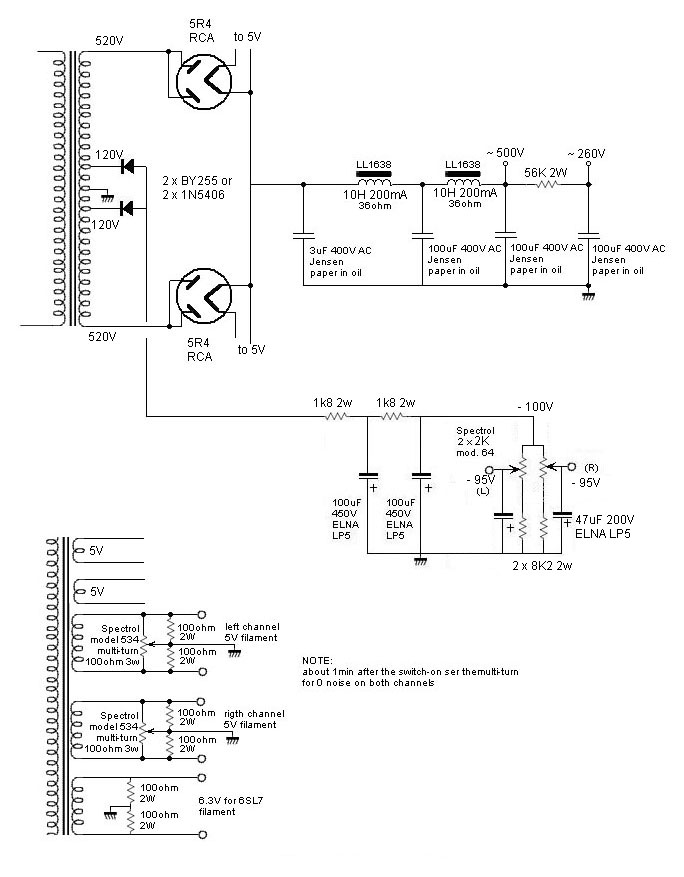
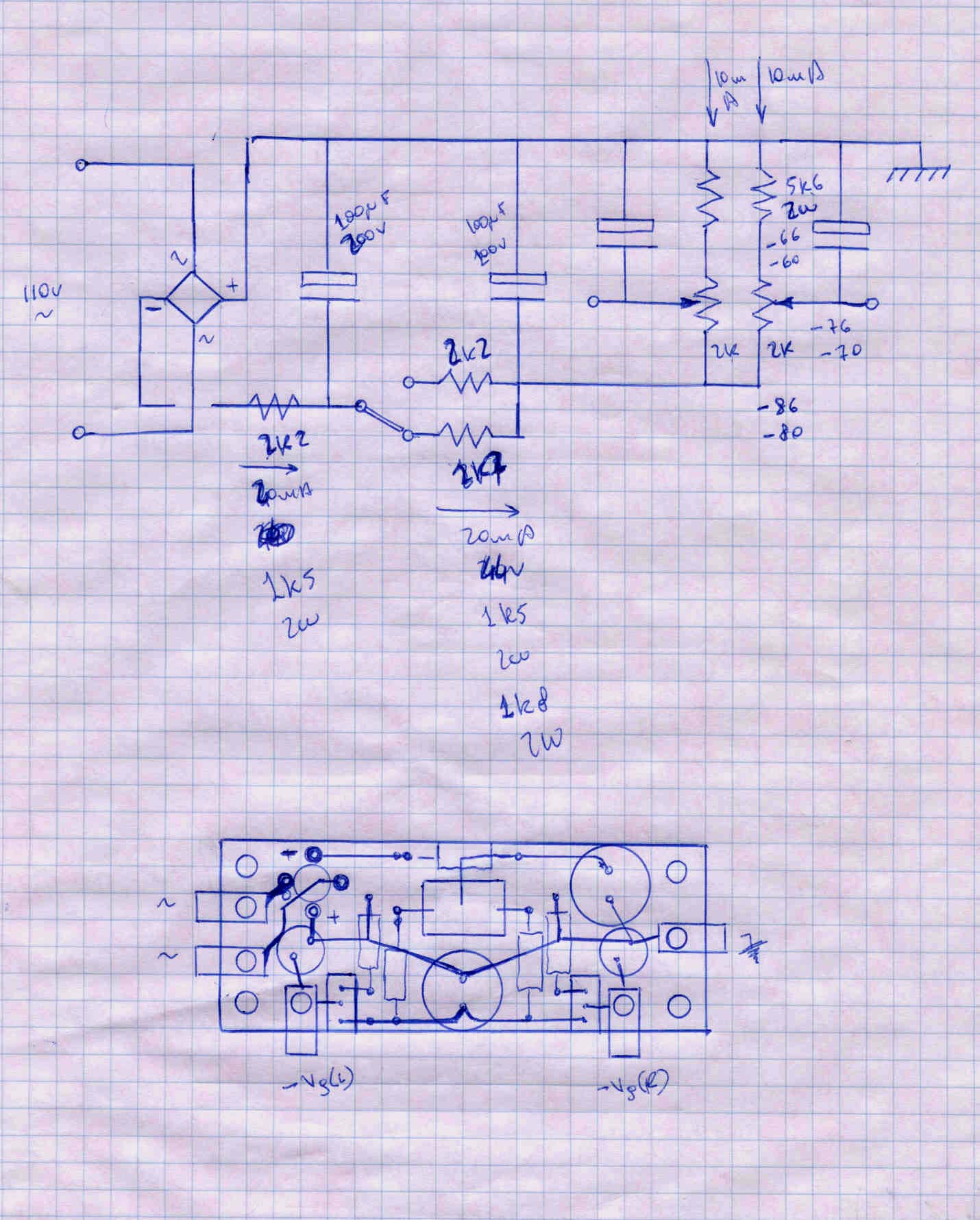
The main schematic
Power supply
Before inserting the 300BXLS tubes in the sockets switch on the amplifier
without the fuse and set the trimmers to get about -90V from the grids
of the 300BXLS and the ground.
After switching off, insert the fuse, insert the 300BXLS and switch
on the amp.
Here is the first version of the schematic using the 5709XH mains transformers
by Antrim custom made on
Studio-M
specification.
another choice with a custom transformer

Here the suggested connection maries and secondaries using the 5709XH
mains transformers by
Antrim
custum made on
Studio-M
specification.
This connection allow the get both anodic voltage about 520V and bias
voltage about 120V.

Digital Input stage
This project gives a first class sonic performance but this can be easily
compromised by a bad input signal so I suggest you don't use preampl.
and use one of my DAC projects instead.
Using one of my top DAC projects all the DIYer's will reach the same
sonic result.
The DAC normally included into commercial CDPlayer (even these of significant
price) have a rather low performance because the common usage of high NFB
operational amplifiers "destroy" the sound given compression effects and
poor soundstage stability.
Sonic results
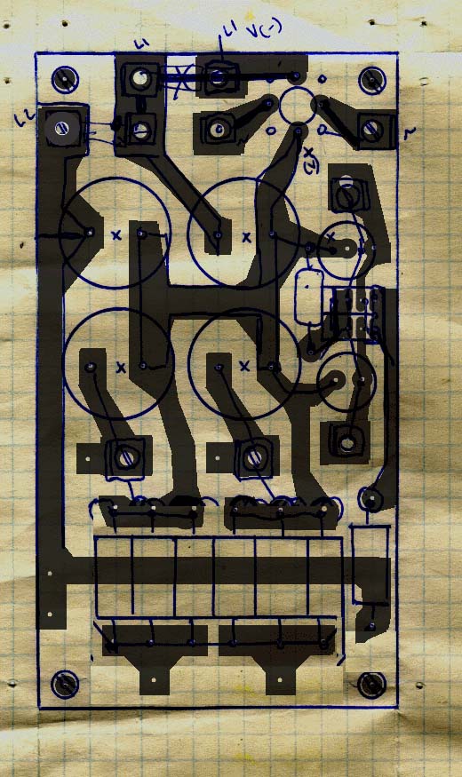
Layout views
click on the images to get real scale
Layout size
click on the images to get real scale
Bias board
click on the images to get real scale