December 2022

|
back to www.audiodesignguide.com |
To get more information contact me at: webmaster@audiodesignguide.com |
|
The H-frame subwoofer December 2022 |
|
|
This is a preview!

 |
Wavecor
SW263WA03
|

This H-frame has been simulated using the Matcad worksheet by Martin King on a Windows XP virtual machine.


MEASUREMENTS
Follows the frequency response of the loudspeaker without the active filter, this is like the simulation model.

You can see the typical resonance peak at 300Hz
determined by the length of the case and this will be this will be reduced
significantly with a high slope filter.
Follows the various
frequency response using the active filter with the dipole compensation.

ACTIVE FILTER
I have got on Ebay an active crossover module to start like base (NE5532 Subwoofer processing circuit).

The original schematic have a big problem, the output voltage change with the frequency setting.


so I have changed some components and the schematic to obtain a good low-pass and to add a dipole compensation.


The main problem of this previous circuit is the 50Kohm potentiometer for frequency change which is not linear but logarithmic so it is not easy find the right position.
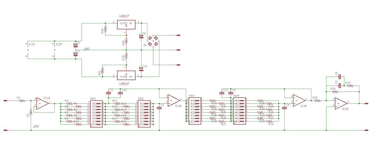
Follows the new filter with a true variable 24dB/oct + dipole compensation

| n. | C1 (nF) | C2 = 2 x C1 | R1 and R2 | C1 (F) | C2 (F) | F (Hz) |
| 1 | 150 | 300 | 3570 | 0,000000150 | 0,0000003 | 210,0 |
| 2 | 150 | 300 | 4120 | 0,000000150 | 0,0000003 | 182,0 |
| 3 | 150 | 300 | 4700 | 0,000000150 | 0,0000003 | 159,5 |
| 4 | 150 | 300 | 5490 | 0,000000150 | 0,0000003 | 136,6 |
| 5 | 150 | 300 | 6200 | 0,000000150 | 0,0000003 | 120,9 |
| 6 | 150 | 300 | 7150 | 0,000000150 | 0,0000003 | 104,9 |
| 7 | 150 | 300 | 8250 | 0,000000150 | 0,0000003 | 90,9 |
| 8 | 150 | 300 | 9530 | 0,000000150 | 0,0000003 | 78,7 |
R1
1Kohm 1/4W 1%
R2
100Kohm 1/4W 1%
R3,R11,R1,R27 3570ohm
1/4W 1%
R4,R12,R20,R28 4120ohm 1/4W 1%
R5,R13,R21,R29 4700ohm 1/4W 1%
R6,R14,R22,R30
5490ohm 1/4W 1%
R7,R15,R23,R31 6200ohm 1/4W
1%
R8,R16,R24,R32 7150ohm 1/4W 1%
R9,R17,R25,R33 8250ohm 1/4W 1%
R10,R18,R26,R34
9530ohm 1/4W 1%
R40,R41
270ohm 1/4W 1%
R38,R39
3000ohm 1/4W 1%
R36
56Kohm 1/4W 1%
R35
3Kohm 1/4W 1%
R37
0ohm
C1,C2,C3.C4,C11,C12 0.15uF WIMA MKP
C5,C8
0.22uF WIMA MKP
C6,C7
470uF 35V
C9,C10
100uF 25V
IC1,IC2
NE5532
U$1
LM317
U$2
LM337
B1
diode bridge 1A
SW1,SW2,SW3,SW4 dip switch 8
way
It is necessary a 3.3uF on output signal to this filter.
FINAL CONSIDERATIONS
AND LISTENING SESSION
PHOTOS


