Solid State Amplifier
2022
INTRODUCTION
After the good experience made on hybrid amplifiers with circlotron
configuration (see the various version of the my
Amplifier
End)
I thought about making a completely solid state amplifier
of this type.
I have analyzed various schemes published online
mainly those on circlotron.audio
(pages) but then I have
decided for a
design vey near to the my
DC Circlotron.
It
is the result of many months of simulations, instrumental testing and
listening test.
This design is inspired to the
Circlotron
US patent n.
4229706
by James W. Bongiorno
and to the
Thorens TEM 3200 by
Frank Blöhbaum.
I have used the
LTspice free simulation tool
to design and optimize this circuit.
This is not a
common solid state amplifier with lot of global feedback, there are only
6dB to reduce output impedance and to linearize the voltage stage.
The my aim was to make a solid state amplifier that sounds like a tube
without feedback so a correction factor of only 6dB was added.
Now
my
Amplifier
End has a real rival and in fact this amplifier with complex
signals it is better and even if it is slightly less soft it is more
neutral, recommended with analog sources or hi-resolution DSC DSD.
The
distortion at maximum power largely depends on the limits imposed by
the power supply voltage chosen for the final stage so you can increase
it without any changes to the circuit.
Like all my amplifiers also this can and
should be driven directly by a CD, DAC or
Phono pre-ampl.
The main benefit
of a Circlotron design is an high power amplifier with no switching output stage like a pure
class A but higher efficiency, with only 1A bias current still
1mA
with 2.3A on 8 load.
You can
increase the output power to 60W on 8ohm changing the chassie and
increasing the power supply voltage of the output stage.
Specifications:
Pout = 50W on 8ohm
with 2 x 33VDC and Vin=0.42Vrms Thd=0.6%
Pout =
90W on 4ohm with 2 x 33VDC and Vin=0.42Vrms Thd=1.3%
Pout = 18W on 8ohm no-switching with 1A bias
(see simulation)
Pd = output stage at 35VDC = 70W each channel with 1A bias
Zout = 178mohm with the Exicon (see
simulation)
Ft(-3dB) = DC - 2MHz at -3dB
Global
feedback = 6dB
Output DC offset about 50-90mVDC (because there is no
active DC serve)
Please do not touch with multimeter probe the mosfet gate after the power on because this
operation will destroy the mosfet.
If possible add
your comment on this amplifier or post photos of your Solidstate 2022
on:
diyaudio.com / Solidstate 2022 - Hi-end amplifier
|

|


SCHEMATIC
These are the main characteristics:
- dc coupled of
all stages
- no
capacitors on the signal path
-
high slew-rate
- good damping factor near to a
solid state
amplifiers with high feedback
- no switching output stage like a pure class A
- high efficiency because
only 70W of consumption per channel
- only single ended stages
- only a single output device
-
only a transconductance amplifier with I/V
- global feedback easy to modify without high
frequency compensation
- full balanced circuit but it accept also
un-balanced input signal
As my other Circlotron amplifiers the
ECW20N20
mosfet are the first choice to get a good
damping factor, a low distortion, a high output power also without
global feedback and it is not necessary a thermal compensation of Vgs.

PCB
This is the last pcb version


J1,J2,J3
J113D74Z
T1,T2
BC546ABU
T3,T4,T5,T6 BC556B
T7,T8
MJE340
U$1,U$2
ECW20N20-S or
ECW20N20 or
2SK1058
R1,R2
100Kohm 1% 1/4W Vishay Dale RN55
R3,R4,R7 1Kohm
1% 1/4W
Vishay Dale RN55
R8
500ohm 1% 1/4W
Vishay Dale RN55
R5,R6
47ohm 1% 1/4W
Vishay Dale RN55
R13,R14
470ohm 1% 1/4W
Vishay Dale RN55
R9,R10,R11,R12 15Kohm
1% 1/4W
Vishay Dale RN55
R17,R18
3900ohm 1% 1/4W Vishay
Dale RN55
R15,R16
10Kohm 1% 1/2W
Vishay Dale RN65
R19,R20 2700ohm
5% 2W
Vishay PR02
R21,R22 2000ohm 1% 1/4W
Vishay Dale RN55
R23,R24
120 or 240ohm 1% 1/4W
RN55
bias 120ohm with
ECW20N20
R28,R29
900ohm 1% 1/4W
Vishay Dale RN55
R25,R31
1Kohm multi turn trimmer Bourns
3296W-1-501LF
RGND 100ohm
1% 1/4W
Vishay Dale RN60 (not necessary for dual mono conf.)
RGROUND 10ohm 5%
2W Vishay PR02
(see photo)
C1,C2
100uF 50V UFG Nichicon
C3,C4
1uF MKP or MKT
C5,C6
not used
CIN
1uF MKP or MKT to use in parallel to R2 if only un-bal input is used
F1,F3
FUSE 5A FAST
KK1,KK4 HEATSINK SK104
13.4C/W
513002B02500G (cod. MOuser
532-513002B25G)
The connections are 63862-1 (CUT STRIP)
by TE Connectivity / AMP (cod. Mouser 571-63862-1-CT,
cod. RS 718-7987)
CZ
0.1uF Vishay
F339X1
RZ
10ohm 2W
Vishay PR02
The driver stage need a regulated power supply module to
have a stable +36VDC and -36VDC.
The normal linear regulator does not support
40V input so I have design a shunt regulator following the application note in
the datasheet of TL431 and I have optimized
this circuit with
LTspice.
In the pcb there are the pins
to connect all the secondaries of the r-core transformer and also to get the DC
protection power supply.


D1,D2,D3,D4
UF5407
C1,C2
4700uF 50V +105°C Nichicon 20 x 40mm
C3,C6
10pF
C4,C5
1nF
R1,R2,R3,R4
47ohm 1W (use only R1 and R4 for dual mono configuration)
U$1,U$2
TL431
R5,R9
1Kohm 1% 1/4W
R8,R11
15Kohm 1% 1/4W
R6,R10
1100ohm 1% 1/4W
R7,R12
100ohm 1% 1/4W
Q1,Q4
BC556
Q2,Q3
MJE350
C7,C8
22uF 50V
UFG Nichicon
KK1,KK4 HEATSINK SK104 11C/W
513102B02500G (cod. MOuser
532-513102B25)
PCB
Ebay shop for the PCB
Ebay
shop for the PCB with 2 x PSU
JFET SELECTION
The main problem of this project is the fet selection necessary
to get the max performances.
This design using a little feedback cannot
compensate the large differences between two fet J113 therefore it is necessary
to buy more pieces and make a selection for a matching.
Below I report 2
measurements made with a different selection of these components.
At this time I am testing the
Peak DCA75 Pro semiconductor analyser
to check the J113 differences but I will give a procedure for
making a selection without purchasing this special tools.

Here the plot of measurements of 3 different J113 fet.

Here
the plot of measurements of matched J113 fets.

An alternative cheap method to match the fet is this
procedure:
-
before solder output mosfet
-
add a jump on R21 and R22 (see on photo yellow wire)
-
set R8+R25 = R7 = 1Kohm
-
power on driver stage
-
set R31 to have 0volt on R19
-
using Arta or other software generate from teh pc a
1KHz sine wave with a level about 0.42Vrms
-
measure the driver output on R19 and R20
-
change J113 until both the
output give 10Vrms

STARTUP PROCEDURE
- 1. Verify the power supply voltage on driver power module +36VDC and
-36VDC
- 2. Set both trimmers in the middle, both the end of the path can be
identified by listening to the slight click
- 3. Connect a multimeter at the connection point between R23 - R28 and
ground
- 4. Give the power supply only to the driver stage
5. Rotate the R31
trimmer until you read a voltage near the 0v
-
6. Connect a multimeter at the connection point between R29 - R24 and ground
- 7. Rotate the R25 trimmer until you read a voltage near the 0v
- 8. Repeat again point 5 and 7 until you read about 0v on both these
points
- 9. add a 0.1ohm in series to the mosfet power supply so on the
connection before one fuse to very the bias current of output
9. Connect the power supply to the output
stage
- 10. Turn the trimmer R31 to read 0V on terminal OUT1
- 11. Turn the trimmer R25 to read 0V on terminals OUT1 and OUT2
- 12. Check again both these points and modify the trimmer position if
necessary
- 13. Verify the bias current measuring the voltage across the 0.1ohm
resistance
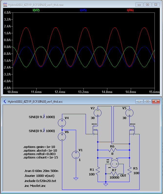
SIMULATION

Frequecy response with Exicon mosfet about Ft(-3dB) = 2.5MHz

Zout=178mohm

Follows the simulation of the distortion at 23Vrms on 8ohm 66W with 2 x
36VDC, about 0.8%.

Simulated noise on power supply module output.

MEASUREMENTS
ECW20N20 version with driver +36VDC and output stage at 2x 33VDC and 6dB
global feedback
Follows some measurements using un-balanced input signal.


2SK1058 version
with driver +-35VDC and output stage at 2 x 36VDC, load
8ohm and 6dB global feedback.
Follow the distorsion at 17Vrms on 8ohm = 36W, simulated Zout about 0.5ohm.


DISTORTION CONTROL
In a direct comparison with my Amplifier End which uses
a tube as a voltage amplifier, an interstage transformer and the same output
mosfets, the sound of this solid state amplifier remains more fatiguing.
This sensation was not present in the prototype which did not have the selected
fet but had a higher distortion so I tried to unbalance the 2 feedback resistors
and I obtained the desired effect by increasing the second harmonic.
Follows the measurements with various values where it is verified that a small
variation is enough by adding 56K in parallel to 39K on the negative line and we
obtain the same harmonic decay of the amplifer end and another listening
pleasure.

| 1 path |
parallel |
2 path |
diff. % |
thd )%= |
| 3900 |
none |
3900 |
0 |
0.18 |
| 3900 |
68000 |
3688 |
5,4 |
0.23 |
| 3900 |
56000 |
3646 |
6,5 |
0.28 |
| 3900 |
47000 |
3601 |
7,7 |
0.34 |
| 3900 |
39000 |
3545 |
9,1 |
0.42 |
TRANSFORMERS
It is possible to use any trasformers from 20V to 30V
with a power about 200-300VA but in any case 2 separated secondaries are
required for each channel.

The my choice is a RS Pro Encapsulated Transformers 2 x
25V 225VA (cod. RS RS123-4028)

The transformer for the driver stage is the
LITE R26-10 (diyclub.biz)
an r-core 30VA
with 2 x 9V 3A and 2 x 18V 0.5A
POWER SUPPLY

Following
the experince of my last amplifiers I have used Schottky Fast Soft recovery
diodes in any section of the power supply but you can use normal 36A diode
bridge like the IRF 36MB60.
To create a bridge with
these TO220 diodes I have created a simple pcb.

Noise on power supply module output.

CHASSIE

In order to dissipate all the heat generated by this
amplifier in my case I chose this container by
HiFi 2000.
Dissipante 03/300B 3U 10mm
SILVER or
BLACK
Product Code: 1NPD03300B
or 1NPD03300N
Used for the 3U 300mm deep chassis temperature
coefficient 0,40 C°/W
2
x 33V
1A = 66W 66W * 0.4C°/W = 13.3C° + 25C° =
38C°

Inner baseplate for
Dissipante 300mm
Product Code:
1BASEPD300

PROTECTION CIRCUIT
Any
serious solid state amplifier need a protection circuit because a fault on
output transistors or mosfet can destroy the loudspeakers.
The
Cirlclotron design never will produce an high dc output but I suggest to use a
dc protection circuit.
I have decided to use
2 x AIYIMA 2.0
Digital Power Amplifier Speaker Protection Board Delay Relay Speaker Protection
available on Alixpress online shop.
This module use 2 optoisolator
PC817
for each input and are necessary only some
little changes to increase the start-up time.
It is not necessary modify
this module with 220Kohm and diode.


SOFT START
START AND TEMPERATURE PROTECTION
I am using this module got on
Alixpress because it incluse a soft-start
and a temperature protection at 75°.


1NO1NC Momentary switch from
Alixpress
PHOTOS
The first photos
are relative to the test environment.


Here some photos of the test environment to compare the switching power supply
to traditional.


Here some photos of the final environment


COST
| Qty |
model |
brand |
unit price (euro) |
total price (euro) |
shop |
| 4 |
ECW20N20 |
Excicon |
12 |
48 |
|
| 4 |
10000uF 50V |
Nichicon |
6 |
24 |
www.partsconnexion.com |
| 2 |
Toroidal transformers |
|
60 |
120 |
|
| 1 |
R-core transformer |
|
40 |
40 |
alixpress.com |
| 16 |
Diodes for the bridge |
On-semi |
2 |
32 |
|
| 1 |
Chassie |
Hi-Fi2000 |
170 |
170 |
www.hifi2000.it |
| 2 |
DC protection module |
|
10 |
20 |
alixpress.com |
| 1 |
Soft start |
|
10 |
10 |
alixpress.com |
| 1 |
connectors |
|
36 |
36 |
|
| 1 |
other items |
|
50 |
50 |
|
| |
|
|
total |
550 |
|
