


|
back to www.audiodesignguide.com |
To get more information contact me at: webmaster@audiodesignguide.com |
Hi-End Class A-AB Balanced Circlotron Hybrid
Amplifier
started on January 25 st ,2011
|
|
|
|
|
INTRODUCTION
After the incredible and unexpected result of the Hybrid 2011 amplifier I am searching to increase the performance on measurements adding these features:
I don't know if this new design have the same sound of the first version so I will try to create a direct compare.
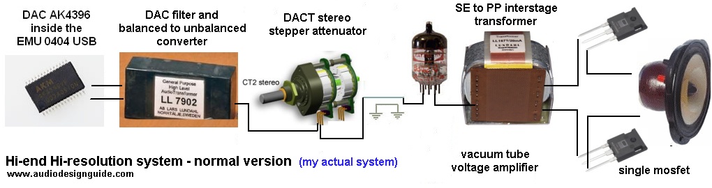
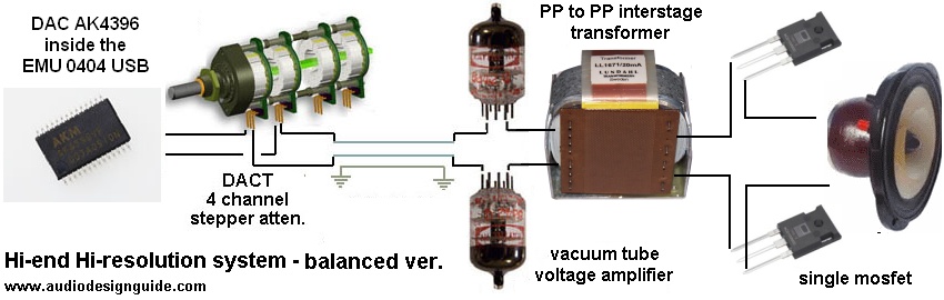
In the following images are show the signal path of these two versions.
work in progress ................................
INTER STAGE TRANSFORMER
The quality of the interstage transformers is very important in this design and
you cannot use any other type without compromise the final result.
The normal Lundahl
LL1671/20mA is very good but you can ask for the
Amorphous strip
core version used in my
Hi-end
headphone amplifier and in my
DAC End.
|
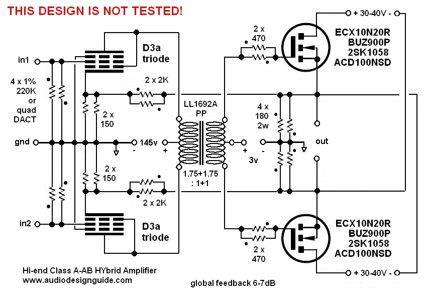
The
Spice simulation show an incredible
slew-rate (20V in 200ns) because the mosfet are driven with a tube with a low
internal resistance (near to 2Kohm) and an interstage transformer with a turn
ratio 2:1 reduce it (4 times) this value (2Kohm / 4 = 500ohm) (here
the .cir). MOSFET
In my test
2SK1058 (Hitachi/Renesas)
and
ECX10N20R are much better than BUZ900P
(Magnatec) as
distortion value but the
ECX10N20R (Exicon) are better than
2SK1058 because have the same distortion value but a better damping
factor.
If we increase the power supply to 40
or 45VDC the
ECX10N20R show a limit and for all the best bias point is 1000mA.
In the simulation the output impedance is about
630mohm on all the
frequency range with the mosfet
ECX10N20R and about 1 ohm using the 2SK1058
and
ECX10N20R. |
|
VOLTAGE AMPLIFIER
To get a good output distortion decay in any condition I
have decided to use a single tube in this stage.
I have searched a tube with a very good linearity for large swing and low anodic
resistance to drive the output stage without problems.
This tube should have an amplification factor
greater than 40 to connect this amplifier
directly to the CD player or phono pre-ampl.
To get 20w on 8ohm we need:
P=V * I and I = V / R =>
P = V * V / R => V = sqrt (P * R ) = 12.5Vrms
so if we want a sensibility of 0.5Vrms we need
Amplifier factor tube = 12.5 / 0.5 = 25
Using the LL1671/20mA with the turn ratio 4:1:1 => 2:1 we need a amplifier factor
tube of 50.

|
Many of these tubes have a plate resistance about 2Kohm but only the D3A, 6C45 and 5842 have an amplification factor greater than 40. D3A specifications in triode connection:
|
6C45 specifications:
|
5842 specifications in triode
connection:
|
|
CURRENT AMPLIFIER
The most simple design to create a class A current amplifier is the
mosfet.
This design is inspired to the
Circlotron
US Patent n.
4229706 by James W. Bongiorno and to the
Thorens TEM
3200.
POWER SUPPLY
I have design the power supply to
follow a single ended amplifier style but you can use a common solid state
design.
The CLC power supply skip any noise problem and it is superior to any pure
capacitor design also if large value are used.
In the following simulations with PSU Designer II you can see the big difference
in residual noise, with CLC type we get a pure sine wave so it mean low
harmonics.
The Hammond 159ZJ (L=10mH Rdc=0.16ohm
Imax=5A) used in this amplifier are not difficult to integrate in any amplifier
because these have a compact size and these are not expensive.

There are many good capacitors to use in audio amplifier power supply but only few of these give hi-end performances:
For this project I have decided to use the Nichicon Super Through on output section and BlackGate (old stock) on vacuum tube stage because both these types will give extreme performances.
To increase the speed of the power supply has been inserted a 39uF Solen MKP in parallel to the electrolitycs.
It is not necessary a DC filament with slow turn-on but it increase the vacuum tube filament and it can be used also for the mosfet gate bias voltage.
MEASUREMENTS
PHOTOS
CONNECTION GUIDE
WINSPICE SIMULATION
To optimize the circuit I have simulate it with Winspice.
PROTECTION
see Amplifier End