|
back to www.audiodesignguide.com |
To get more information contact me at: webmaster@audiodesignguide.com |
USB DAC 2 - first tests
April
1 st , 2012 -
working in progress ......
INTRODUCTION
The high resolution PCM at 96-192KHz 24bit offer the
possibility to have a good quality digital signal near to the analog.
The first problem to create a DAC to play 96-192KHz 24bit tracks is find a
good USB to I2S converter.
I have tested these USB-I2S interfaces and I have found very big
differences in the sound:
After 3 tests in 2 different rooms, 3 different systems, with 3 my friends I can affirm that XMOS module by Lorien is the best. There are many differences in the listening and only the XMOS has an open sound, full of details and never tiring. With the XMOS all musical instruments are easily recognizable in the sound stage.
In my first test I
have used the Wolfson WM8740 DAC chip with an internal active I/V stage but
to increase the sonic performances I have decided to use the AD1955 and
PCM1794 with
passive I/V.
I consider the resistors the best method to create a passive I/V because
using the transformers the result is not good for many parameters.
I have tested 2 different output stages:
The second is more expensive but it sound a little better than my hybrid, as details and soundstage there are no differences but playing some audio tracks you can prefer it.
To get the best sonic
performances is necessary to use a pair of 2.2uF
Jantzen
Audio Superior Z-cap in both output stages and 39uF 400V
Solen MKP in the power supply.
The quality of vacuum tubes is a condition necessary to get a good sound so I
have used 5687WA by Jan Philips and
E82CC by original Mullard but there are many other
new production tubes to
use.
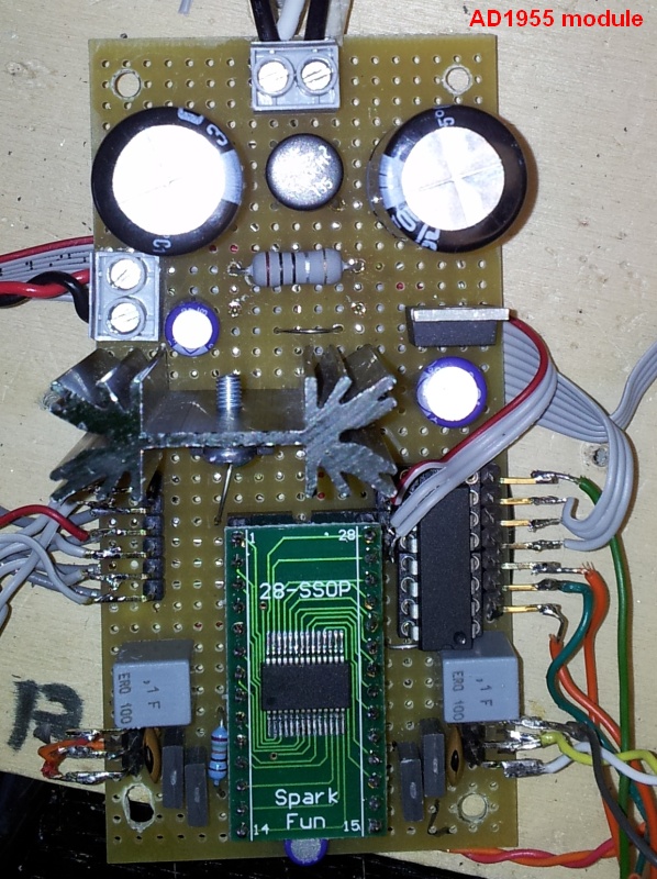
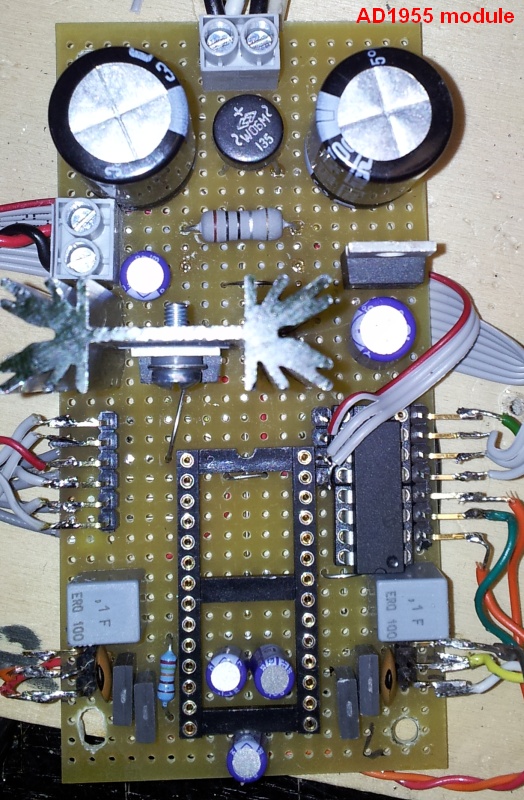
AD1955 DAC SCHEMATIC
The AD1955 analog outputs are not current source like the most of DAC chips but it has a current sink outputs so the I/V resistors are connected to the analog positive power supply instead of the ground (TI doc.).
Using this DAC chip is necessary set some registers to play audio tracks at different sample rate so I have used a little 16F684 Microchip PIC with a my custom firmware.
Others DAC chips
like the TI PCM1794 and Wolfson
WM8740 has a master clock detection circuit that
automatically determines the relationship between the master clock frequency
and the sampling rate.
In a
direct comparison the AD1955 sound much better than PM1794 and WM8740
but I would like to do a new test with these DAC chips.
The AD1955 have an on-chip click less analog volume control without lost in resolution and I have implemented this in the PIC firmware so we can save the money necessary to buy a DACT stepper attenuator.
There are very few components to create a complete DAC so you can assemble this in few minutes on a strip board.
The main problem is solder the AD1955 in SSOP package but you can find on Ebay stores some chips on DIP adapter.

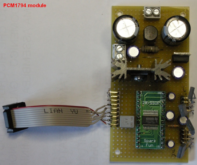
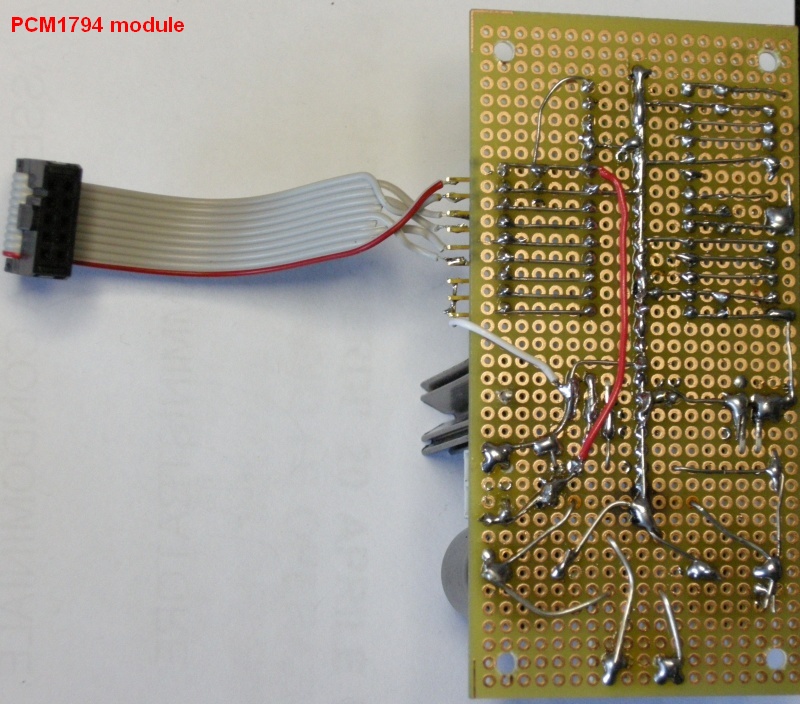
PCM1794 DAC SCHEMATIC
PCM1794 DAC borad need very few components so you can assemble this in few minutes on a strip board.
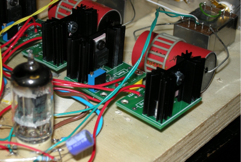
OUTPUT STAGE SCHEMATIC 1
The
Raleigh Audio Line Stage
clone is a Differential parafeed line stage push-pull with a pair of CCS
(constant current source) to isolate the power supply from the
signal.
A 2.2uF parafeed capacitor isolating the output transformer from the power
supply current so is possible to use little output transformers with amorphous
core.
 |
The CCS are
K&K Audio modules
with large heat sink kit, two for each channel. I have used the normal type CCS but it is possible to use the cascode type. |
 |
OUTPUT STAGE SCHEMATIC 2
My Hybrid output stage
with the power supply used to test both output stages, IRF840 are 4 x IRF720 and 2 x
IRF740.
The power supply use a 3A adjustable regulator with soft start for the filaments
at 12.6V DC and a dual mono Virtual Battery for the high voltage about 270V DC.
It is necessary an output relay to prevent the output of the voltage peaks
during the switching on and off.
In the PCB are present the components to create a version with balanced and
unbalanced outputs but if you don't need balanced output simply do not fit some
components (Q4-5, R66-67, R72-73, R35-38, R39-42, R43-44. R45-46, 2 x 2.2uF).

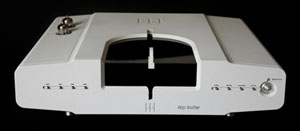
PHOTOS
 |
 |
 |
 |
 |
 |
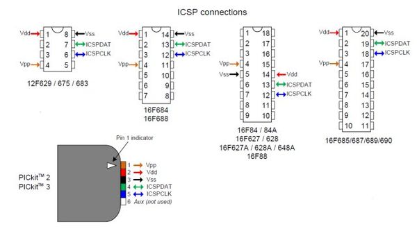
AD1955 PIC FIRMWARE
Using this DAC chip is necessary set some registers to play audio tracks at different sample rate so I have used a little 16F684 Microchip PIC with a my custom firmware.
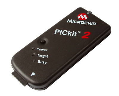
The PICkit™ 2 Development Programmer/Debugger (PG164120) is a low-cost development tool with an easy to use interface for programming and debugging.
There are also some cheaper clones on Ebay stores.
Folllows the complete source to compile with the command:
picl.exe -16F684 AD1955_16F684_v2_volume_sampler.c
#include  <pic.h>
#include  <stdio.h>


__CONFIG(WDTDIS & INTIO & UNPROTECT & MCLRDIS & PWRTEN );

#ifndef	XTAL_FREQ
#define	XTAL_FREQ	4MHZ		/* Crystal frequency in MHz */
#endif

#define	MHZ	*1000L			/* number of kHz in a MHz */
#define	KHZ	*1			/* number of kHz in a kHz */

#if	XTAL_FREQ >= 12MHZ
	#define	DelayUs(x)	{ unsigned char _dcnt; \
				  _dcnt = (x)*((XTAL_FREQ)/(12MHZ)); \
				  while(--_dcnt != 0) \
				  continue; }
#else
	#define	DelayUs(x)	{ unsigned char _dcnt; \
				  _dcnt = (x)/((12MHZ)/(XTAL_FREQ))|1; \
				  while(--_dcnt != 0) \
					  continue; }
#endif


#define PORTBIT(adr, bit) ((unsigned)(&adr)*8+(bit))


static bit RST     @ PORTBIT(PORTA, 5);
static bit VOD     @ PORTBIT(PORTA, 4);
static bit VOU     @ PORTBIT(PORTA, 3);
static bit CLK     @ PORTBIT(PORTA, 2);
static bit CSL     @ PORTBIT(PORTA, 1);
static bit DAT     @ PORTBIT(PORTA, 0);

static bit F192    @ PORTBIT(PORTC, 5);
static bit F176    @ PORTBIT(PORTC, 4);
static bit F96     @ PORTBIT(PORTC, 3);
static bit F88     @ PORTBIT(PORTC, 0);
static bit F48     @ PORTBIT(PORTC, 1);
static bit F44     @ PORTBIT(PORTC, 2);

void write_SPI(unsigned int data, unsigned int len);
void DelayMs(unsigned char cnt);
void SetVolume(int);
int Check_sampler(int sampler, int level);


const int values[32] = { 1,3,5,8,12,16,20,25,31,37,45,54,64,75,88,103,120,139,162,187,217,250,288,322,382,440,506,581,667,766,879,1008  };

void main()
{
    int level = 5;
    int sampler = 0;


    PORTA    = 0b00000000;
    PORTC    = 0b00000000;
    ANSEL    = 0b00000000;
    CMCON0   = 0b00000111;  // All comparator disabled
    TRISA    = 0b00011000;  // only RA3 & RA4 are input
    TRISC    = 0b00111111;  // all RC ports are input
    C2IE     = 0;           // disable comparator 2
    C1IE     = 0;           // disable comparator 1
    CCP1IE   = 0;	    // Disables the CCP1 interrupt


    CSL = 1;
    CLK = 0;
    DAT = 0;
    RST = 0;

    DelayMs(250);

    RST = 1;

    DelayMs(250);
    DelayMs(250);
    DelayMs(250);
    DelayMs(250);

    SetVolume(level);

    DelayMs(250);
    DelayMs(250);
    DelayMs(250);
    DelayMs(250);

    SetVolume(level);

    while (1)
    {
       sampler = Check_sampler(sampler, level);

       if (VOU == 0)
       {
            if (level < 31)
                level += 1;

	    SetVolume(level);
       }
       else if (VOD == 0)
       {
            if (level > 0)
	        level -= 1;

	    SetVolume(level);

       }

       DelayMs(50);
   }
}

int Check_sampler(int sampler, int level)
{
   int test = 0;

   if      ( F44  ) test = 44;
   else if ( F48  ) test = 48;
   else if ( F88  ) test = 88;
   else if ( F96  ) test = 96;
   else if ( F176 ) test = 176;
   else if ( F192 ) test = 192;
   else             test = 192;

   if ( sampler == test )
        return sampler;

   sampler = test;

   switch (sampler)
   {
	case 44:   // Interpolation = 8x   MCLK mode = 512 x Fs
	case 48:
	    CSL = 0;
            write_SPI(0b00000000, 8);
            write_SPI(0b00000000, 8);
	    CSL = 1;
	    CLK = 0;
	    DAT = 0;
	    DelayMs(50);
	    CSL = 0;
            write_SPI(0b01000000, 8);
            write_SPI(0b00000001, 8);
	    CSL = 1;
	    CLK = 0;
	    DAT = 0;
	    break;

	case 88:   // Interpolation = 4x   MCLK mode = 256 x Fs
	case 96:
	    CSL = 0;
	    write_SPI(0b00000001, 8);
	    write_SPI(0b00000000, 8);
	    CSL = 1;
            CLK = 0;
	    DAT = 0;
	    DelayMs(50);
	    CSL = 0;
            write_SPI(0b01000000, 8);
            write_SPI(0b00000001, 8);
	    CSL = 1;
	    CLK = 0;
	    DAT = 0;
	    break;

	case 176:  // Interpolation = 2x   MCLK mode = 256 x Fs
	case 192:
            CSL = 0;
    	    write_SPI(0b00000010, 8);
   	    write_SPI(0b00000000, 8);
    	    CSL = 1;
	    CLK = 0;
	    DAT = 0;
	    DelayMs(50);
	    CSL = 0;
            write_SPI(0b01000000, 8);
            write_SPI(0b00000001, 8);
	    CSL = 1;
	    CLK = 0;
	    DAT = 0;
	    break;
   }
   return sampler;
}


void SetVolume(int l)
{
    int vol = values[l];

    CSL = 0;
    write_SPI(vol, 10);
    write_SPI(0b1111, 4);
    write_SPI(0b10, 2);
    CSL = 1;

    DelayMs(50);

    CSL = 0;
    write_SPI(vol, 10);
    write_SPI(0b1111, 4);
    write_SPI(0b11, 2);
    CSL = 1;

    DelayMs(50);

    CLK = 0;
    DAT = 0;
}


void DelayMs(unsigned char cnt)
{
    unsigned char	i;

    do {
	i = 4;

	do {
		DelayUs(250);
	    } while(--i);
    } while(--cnt);
}


void write_SPI(unsigned int data, unsigned int n_bit)
{
    unsigned int bit_mask;
    int i;


    bit_mask = 1 << (n_bit - 1);

    for (i = 0; i < n_bit; i++)
    {
        if ((data & bit_mask) == 0)
	{
	    CLK = 0;
            DAT = 0;
	}
        else
	{
	    CLK = 0;
            DAT = 1;
	}
	DelayUs(100);

        CLK = 1;

	DelayUs(100);

        data <<= 1;
    }
}
AD1955 MEASUREMENTS
DAC with my Hybrid output stage, 3.6Vrms at 0dB
DAC with Raleigh Audio Line Stage clone output stage, 2.8Vrms at 0dB
PARTS
These lists are still not complete .............
| DAC module | ||
| item | description | cost in euro |
| 1 | XMOS USB-to-I2s module by Lucian | 99 |
| 2 | 3300uF 25V | 6 |
| 1 | diode bridge 1A | 1 |
| 1 | 220uF 6.3 OS-CON | 2 |
| 1 | 47uF 6.3V OS-CON | 2 |
| 3 | 10UF 6.3V OS-CON | 6 |
| 4 | Caddock MK132 200ohm | 15 |
| 2 | 0.1uF MKP | 4 |
| 1 | AD1955 | 10 |
| 1 | SSOP-to-DIP 28pim | 3 |
| 1 | socket 28pin | 2 |
| 1 | socket 16[in | 1 |
| 1 | Microprocessor | 3 |
| 1 | Heatsink | 2 |
| 1 | multi use pcb | 4 |
| 1 | LT1085 | 5 |
| 1 | LT1086 | 5 |
| total | 170 | |
| Hybrid output stage | ||
| item | description | cost in euro |
| 1 | pcb | 60 |
| 7 | heatsink | 10 |
| 7 | mosfet | 18 |
| 1 | LM350 | 3 |
| 2 | 2200uF 25V | 6 |
| 1 | 400V 150uF | 5 |
| 1 | 2N2905 | 2 |
| 3 | 220uF 25V | 6 |
| 1 | 200ohm multi turn trimmer | 2 |
| 1 | 33UF 400V | 3 |
| 4 | tube socket | 12 |
| 2 | ECC82 | 40 |
| 2 | 39UF 400V Solen | 40 |
| 2 | 2.2UF Z-Cap | 36 |
| 20 | resistors | 20 |
| 2 | 2N5449 | 3 |
| 1 | custom transformer | 60 |
| 1 | chassie | 70 |
| 2 | RCA connectors | 5 |
| total | 401 | |
| Raleigh output stage | ||
| item | description | cost in euro |
| 1 | pcb | 30 |
| 2 | heatsink | 3 |
| 2 | mosfet | 5 |
| 1 | LM350 | 3 |
| 2 | 2200uF 25V | 6 |
| 1 | 400V 150uF | 5 |
| 1 | 2N2905 | 2 |
| 3 | 220uF 25V | 6 |
| 1 | 200ohm multi turn trimmer | 2 |
| 1 | 33UF 400V | 3 |
| 4 | tube socket | 12 |
| 2 | 5687 | 40 |
| 2 | 39UF 400V Solen | 40 |
| 2 | 2.2UF Z-Cap | 36 |
| 20 | resistors | 20 |
| 4 | CCS | 32 |
| 2 | LL1674 | 230 |
| 1 | custom transformer | 60 |
| 1 | chassie | 70 |
| 2 | RCA connectors | 5 |
| total | 610 | |