the my Hi-End super linear Headphone amplifier without
vaccum tube
by Andrea Ciuffoli - 1992 - 2004
contact me for any problem or question: webmaster@audiodesignguide.com
Introduction
I am publishing this project after many year from its idea and
realization.
The project is born before to start to play with vacuum tube.
At this time I think that this project could be a very interesting
solution if you don't want use vacuum tubes.
I think in any case that my SESS vacuum tube amplifier is the best
solution to drive any headphone with an impedance from 250ohm to 600ohm.
The new simulation, the measurement and the listen test have
demostrated
that this transistor only project is a very hi-end amplifier.
It could drive any kind of headphone, from the 30ohm of a Grado to
the 300ohm of the Beyerdynamic.

The
idea
The schematic has been develop on the idea coming studing the Pioneer
input
stage of the Exclusive series amplifiers A-09 and M6.
The configuration of these amplifers use current mirror and a
pnp-npn follower to
compensate the distortion of the transistors.
If we analize a single section of the M-9 input stage excluding
the dynamic cascode, the input fet, and we replace the current
genarator with a single resistor:

we will get this following configuration.
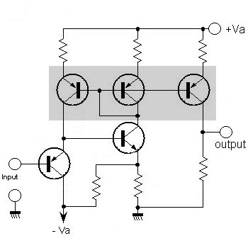
from the original Pioneer specification

The
circuit
The targets are:
- Very low distortion with any load in the range from 22ohm to
600ohm
- Class A operation in any stage
- NO feedback (only dc conpensation)
- All discrete components on the signal path (the operational is
only for the dc compensation)

soon update !!!
The
simulation
The performances of this design has been optimized with electronic
simulation using the WinSpice .3.1
software for Windows.
The WinSpice 3.1 has been
develop by Mike Smith and it is a beatiful port of original spice3f4
develop by Berkeley University of
California.
It can generate waveform plots to individual floating windows and
contains a powerful scripting language
 download the circuit
The result is the following on 200 ohm load with 70mA bias
Fourier
analysis for v(out):
No.
Harmonics: 10, THD: 0.0402076 %, Gridsize: 200, Interpolation Degree: 1
Harmonic
Frequency Magnitude
Phase Norm.
Mag Norm. Phase
--------
--------- --------- p;
----- &
--------- -----------
0
0.000000e+00 -2.15765e-01 0.000000e+00 0.000000e+00 0.000000e+00
1
1.000000e+04 1.065667e+01 -2.23091e-01 1.000000e+00 0.000000e+00
2
2.000000e+04 2.648180e-03 1.002893e+02 2.484997e-04 1.005124e+02
3
3.000000e+04 3.363799e-03 2.139252e+01 3.156518e-04 2.161562e+01
4
4.000000e+04 9.505072e-05 -5.31800e+01 8.919361e-06 -5.29569e+01
5
5.000000e+04 1.483406e-04 -1.20027e+02 1.391998e-05 -1.19804e+02
6
6.000000e+04 9.038702e-06 1.606560e+02 8.481729e-07 1.608791e+02
7
7.000000e+04 1.723391e-05 7.881297e+01 1.617194e-06 7.903606e+01
8
8.000000e+04 1.866338e-06 -3.13638e+01 1.751332e-07 -3.11407e+01
9
9.000000e+04 2.287575e-06 -1.01812e+02 2.146613e-07 -1.01589e+02
on 22ohm load with 70mA bias the output stage go in class AB operation
Fourier
analysis for v(out):
No.
Harmonics: 10, THD: 0.295698 %, Gridsize: 200, Interpolation Degree: 1
Harmonic
Frequency Magnitude
Phase Norm.
Mag Norm. Phase
--------
--------- --------- p;
----- &
--------- -----------
0
0.000000e+00 -2.00760e-01 0.000000e+00 0.000000e+00 0.000000e+00
1
1.000000e+04 5.090969e+00 -2.22745e-01 1.000000e+00 0.000000e+00
2
2.000000e+04 4.032223e-03 -9.19993e+01 7.920344e-04 -9.17766e+01
3
3.000000e+04 1.428727e-02 -6.86804e-02 2.806394e-03 1.540646e-01
4
4.000000e+04 1.228811e-03 -9.04889e+01 2.413708e-04 -9.02662e+01
5
5.000000e+04 2.086553e-03 -1.14260e+00 4.098538e-04 -9.19858e-01
6
6.000000e+04 2.145174e-04 8.655970e+01 4.213686e-05 8.678244e+01
7
7.000000e+04 3.653638e-04 1.789355e+02 7.176705e-05 1.791583e+02
8
8.000000e+04 3.178136e-04 8.800366e+01 6.242693e-05 8.822640e+01
9
9.000000e+04 3.001016e-04 1.782272e+02 5.894785e-05 1.784499e+02
That is a very good result!!
The
components
This project does not use esoteric components but common good
transistors easy to find in any electronic shop.
All the NPN are BC547, all the PNP are BC557 and in the output stage
the final are BD139 (npn) and BD140 (pnp).
These are some capacitors suggested for the ultra fast by-pass 0.01uF -
0.1uF and for the 1uF 50V-63V.
All these components could be find in any normal electronic shop
or from http://www.rs-components.com

About the fast by-pass and as input I suggest to use the very good
Auricap capacitors by Audience.
Each channel will use 4 x 1uF 200V as by-pass onf power supply and 1 x
4.7uF 200V in input.
The high frequency cut-off is composed by the 2200ohm input resistor
and the 100pF Silvered Mica capacitor.
The
layout

and will have this look if we insert the by-pass capacitors
to increase hi-frequency performances.

If you are interested to another layer without pcb see these
implementation by Consuelo
Borghesi.
The Startup phase and setting
Before to power up the amplifier you need to be sure that the bias
control is set for the minimun current otherwise you could destroy the
final stage BD139/BD140.
I know that could be not easy understand which is the rigth way to turn
the trimmer but if you use the suggested Spectrol multi-turn trimmer
you just need to follows this image.

Now you can power up the amplifier with any 12V-0-12V to 20V-0-20V dc
power supply.
Usa a multimeter to measure the voltage accross one of the two output
resistor and start to search your target curent.
Ofcourse the current will be egual to the voltage read because
the value of these resistors is 1ohm.
I suggest a bias current about 50mA and never more than 100mA because
in this circuit there is not a termal compensation (it is easy to add
if you need).
After set the bias current wait 15 minuts to be sure of the value.
The Result by Clio system
The distortion spectrum driving with this amp. an 200ohm load with
about 30mA bias current, is perfect, the distortion is near 0.

and here the distortion driving 22ohm with a bias current about 100mA

The frequency response of first version using an 1uF input capacitor,
the low frequency
cut-off is about 25Hz (-3db) so little too high.

and now follows the result with 10uF input capacitor that is perfect so
a valid value could be 4.7uF

The PCB
That is a 10cm x 10cm board


