
INTRODUCTION

The test will be on the best DAC chips that are the top products of 4 different manufactures: Analog Device, Wolfson, Burr-Brown and Cirrus/Crystal.
|
|
|
|
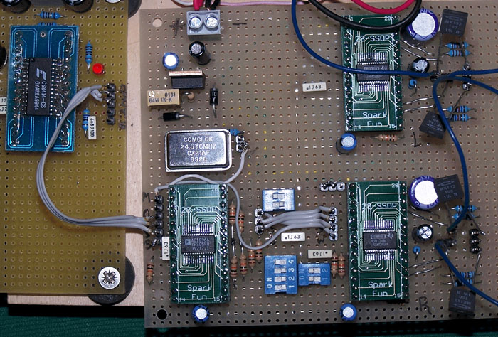
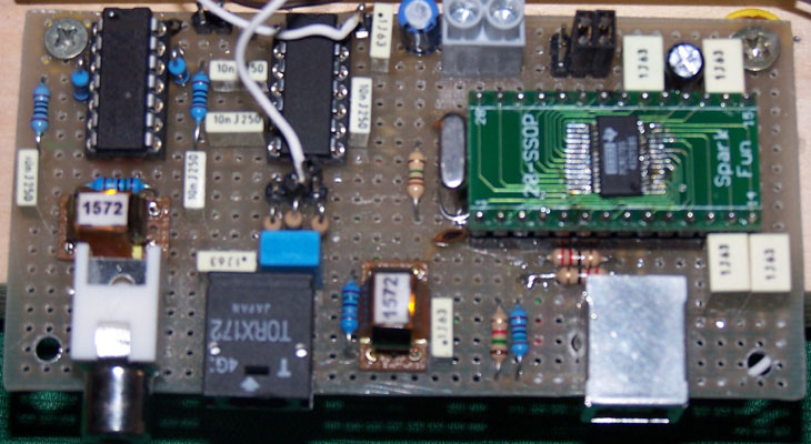
The main problem using these new DAC chips is the small outline packages (28 pin SSOP or 28pin SOIC).
I have found a solution to this problem using the SOIC and SSOP to DIP Adapters produced and sell by Spark Fun.
![]()
On their website there is a valid guide on the SMD reflow soldering (click here)
Follows a simple comparing table for these DAC chips.
| Feature |
Crystal |
Wolfson |
Burr-Brown |
Burr-Brown |
Burr-Brown |
Burr-Brown |
Analog Devices |
Analog Devices |
| DAC chip |
WM8740 mono | PCM1798 | PCM1798 mono | PCM1794 | PCM1794 mono | |||
| Resolution |
24 bit |
24 bit | 24 bit |
24bit | 24 bit |
24bit | 24 bit |
24 bit |
| Max Sampling frequency [KHz] | 192 | 195 | 200 | 200 | 200 | 200 | 192 | 192 |
| THD @ 0dB & 44.1KHz [%] |
-100dB |
-104db | 0.0005 | 0.0005 | 0.0004 | 0.0004 | -123dB | -110dB |
| THD @ 0dB & 96KHz [%] |
-100dB |
-104db | 0.001 | 0.001 | 0.0008 | 0.0008 | -133dB |
-110dB |
| Dynamic range 44.1KHz [dB] |
117 |
117 | 123 |
126 | 129 |
132 | 120 |
123 |
| Dynamic range 96KHz [dB] | 117 |
117 | 123 |
126 | 129 |
132 | 120 | 123 |
| DAC S/N | 100 |
120 | 123 |
126 | 129 |
132 | 120 db |
120 |
| Outputs peak to peak | 1.4Vpp | 2Vrms | 4.0mA | 8.0mA | 7.8mA | 15.6mA | 8.64mA | 17.28mA |
The main differences are:
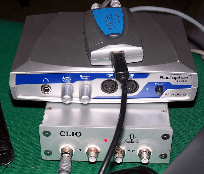
I have used in all the measurements the Clio system by Audiomatica with the Transit by M-Audio to use the USB port of my portable pc (instead of the PCI audio board) and with the Audiophile USB by M-Audio to have a spdif ouput.
POWER SUPPLY
To build the test I have created an evaluation board for each chip and a common environment with all the necessary power supply.
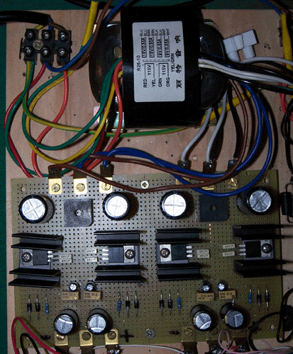 |
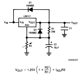
The DAC power supply use the
LM317 and LM337 to
create the +5V, -5V, +12V and -12V. I have used a good 50W R-Core transformer get from DIY Club at a very good price. For a fine tune of output voltage I have used a Spectrol multiturn cermet trimmer (R2) with a value of 1Kohm for the 5V and 5Kohm for the 12V. Reverse diodes and capacitors polarity to get the schematic of the negative voltage.
|
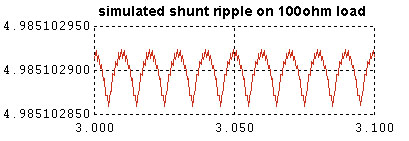 |
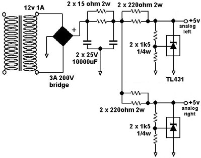
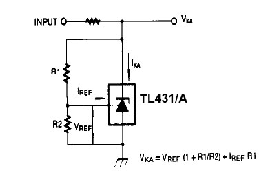
For the analog section of DAC has been used a shunt power supply using TL431 to get the max sonic performances (not visible in the photo). For the PCM179x and AD1955 configurated in mono mode should be used a separated shunt for each DAC chip to get the max separation from left to right channel (see schematic to the left). After the listening test the shunt regulator has been eliminated |
 |
 |
OUTPUT STAGE
The DAC board has been connected to different output stages:

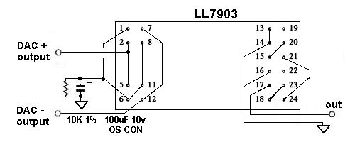
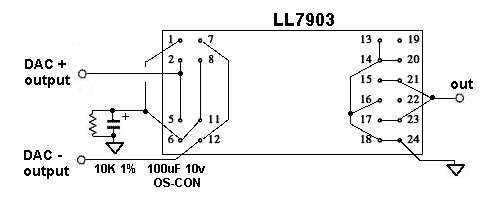
For the LL1554 and the LL7903 has been tested many connections: primaries and secondaries in series or in parallel to get the best result.
The LL1554 has been excluded after the first test because the distortion at low frequency has been considered too high.
The measurement with the LL7903 are perfect at any frequency.
|
|
|
 |
|
 |
INPUT STAGE (opzional)
 |
The DAC boards could be used without an input/receiver boards if you got a CD transport with I2S bus like the CD-Pro2M. |
For this project I have develop an input stage with all the inputs: spdif, optical toslink and USB.
Using the PCM2704 no driver are necessary to use the USB Audio device with Windows XP and the most Linux distributions.
The new input/receiver board use the new CS8416 with integrated input switch.

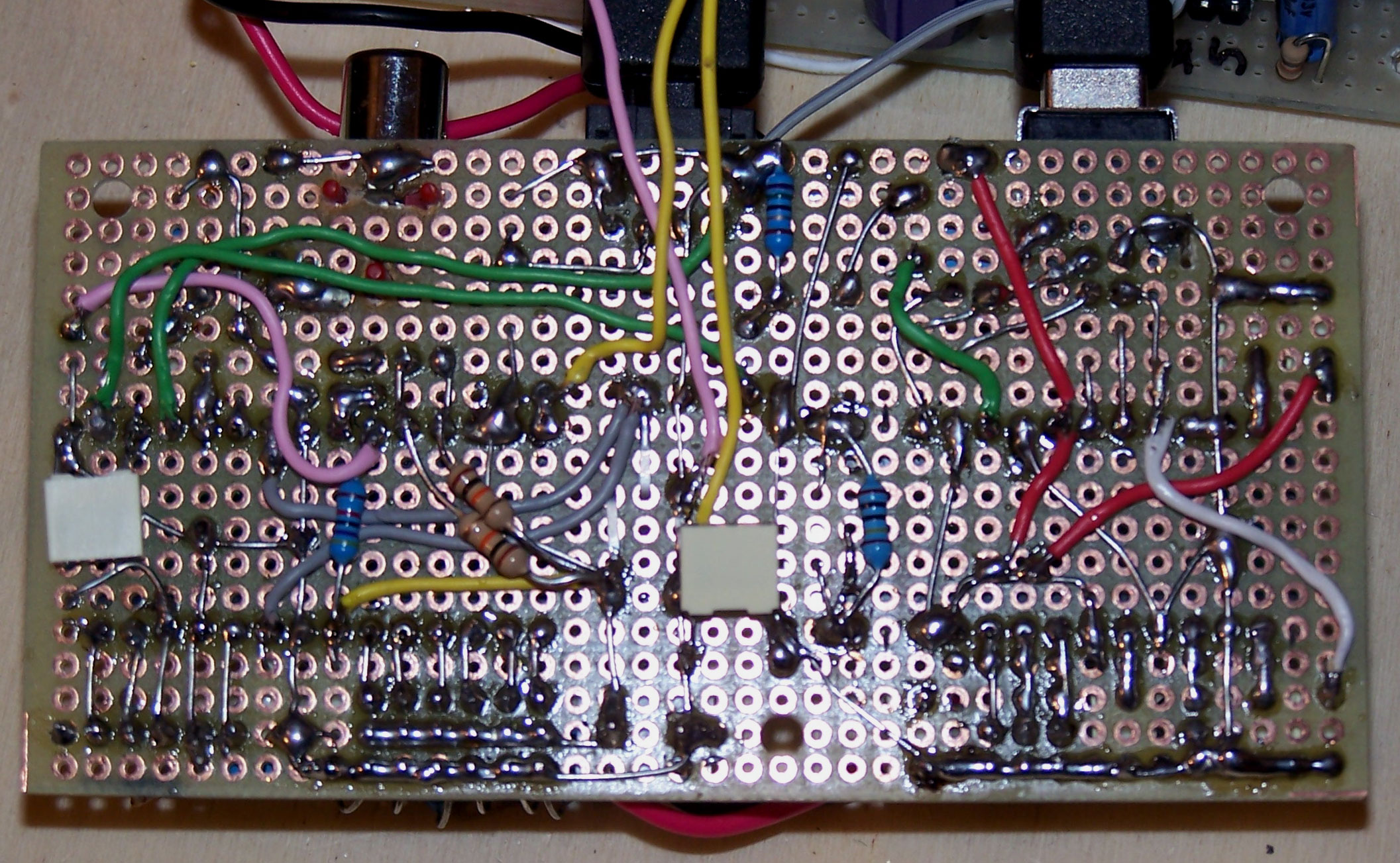
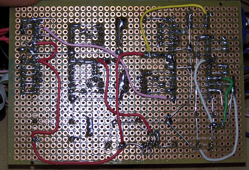
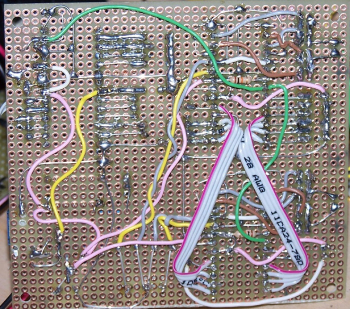
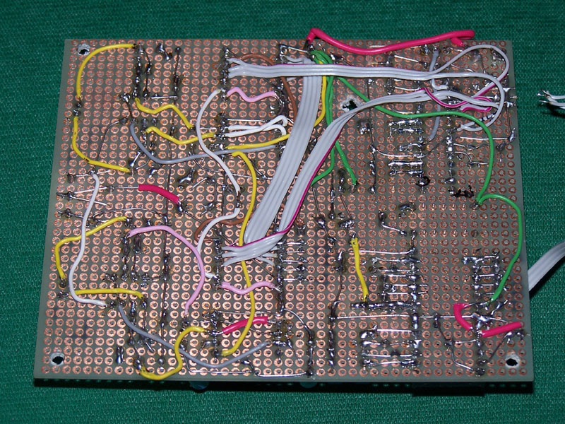
To view the bottom of this simple board click here.

OLD BOARD
The input selector does not use relay but only a high speed logic NAND chip 74HC00.
The spdif signals are converted to TTL level with a circuit seen on the following website and using a high speed logic inverter 74HC04.
All the input have a galvanic isolation using the Lundahl LL1572 transformer before the CS8414.
AD1895 / AD1896 ASRC
After many time lost with Cirrus CS8421 my choice for the ASRC has been the AD1895 or the AD1896.
Asynchronous sample rate conversion is converting data from one clock source at some sample rate to another clock source at the same or different sample rate.
This components are very important in the Jitter reduction.
There are some articles on this function on:

 |
 |
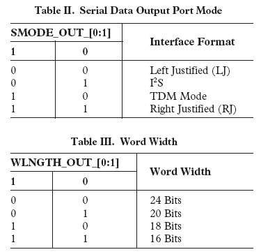
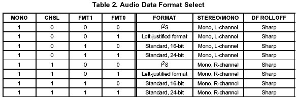
| The input has been fixed to I2S protocol but the
output can be changed with the dip switches. The pin 28 has been fixed to ground so the AD189x will be always a master on output. |
The dip switches and the 10Kohm resistors are not necessary in a final product because you can directly connect the configuration pins to +V or ground.
In this case if you see in photo the switch on the position "ON" connect the pin to ground otherwise if you see the switch near the numbers connect is to the pin to +3.3v.
CS4397

To view the bottom of this simple board click here.


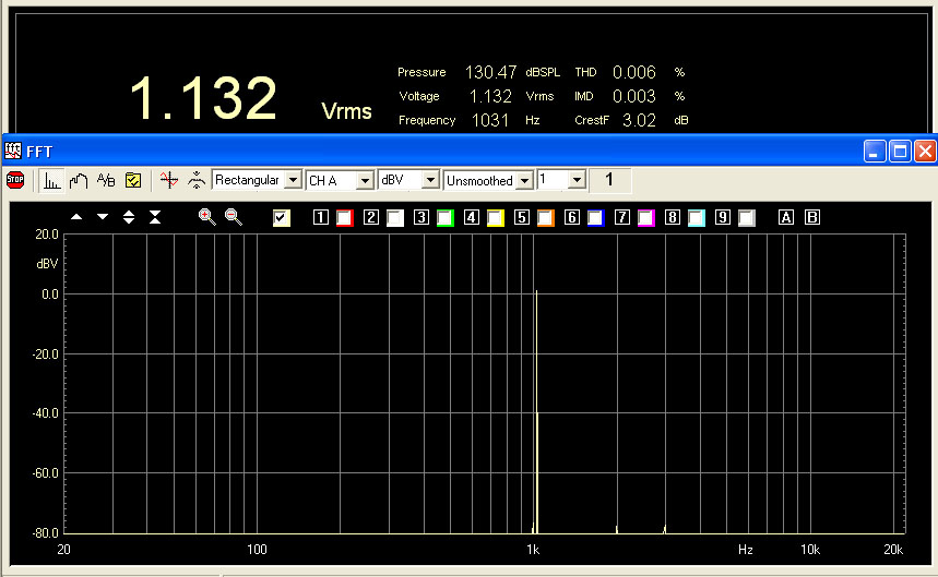
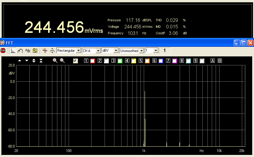
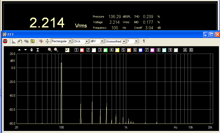
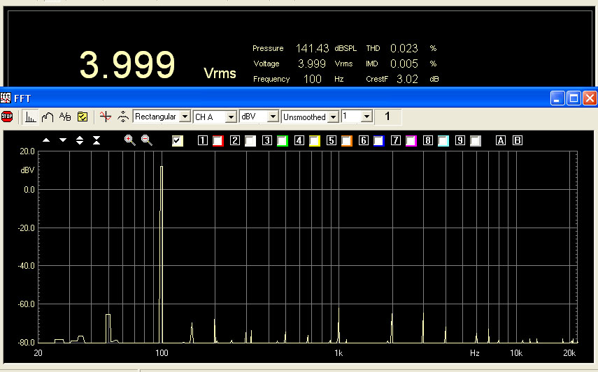
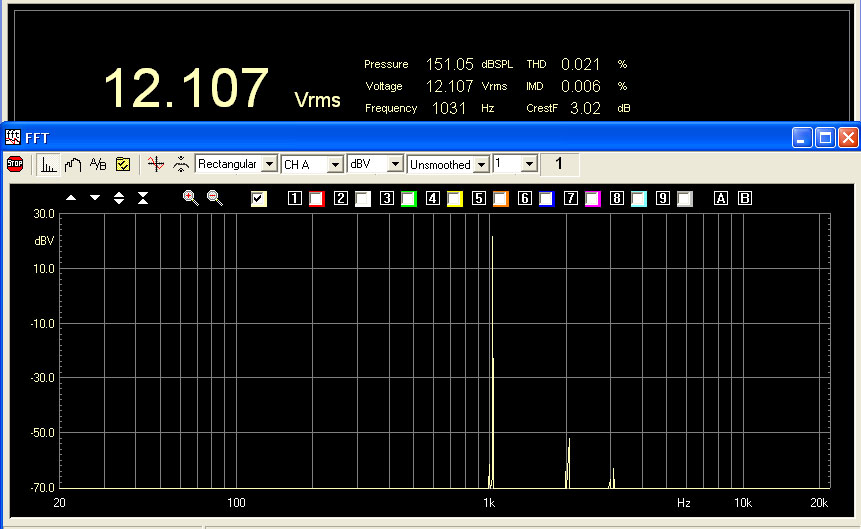
Follows the measurement on DAC board outputs.
In this first configuration the output load should be 10kohm or more.
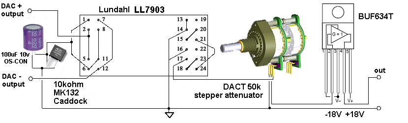
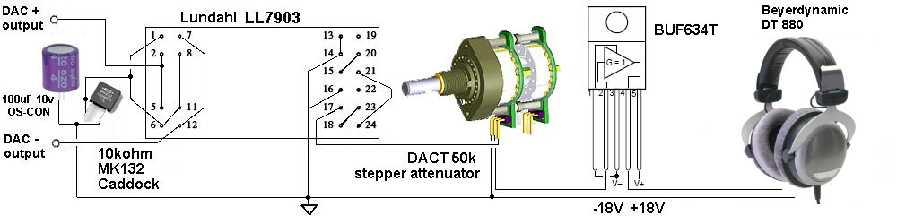
In this case the load to apply should be 100Kohm (the DAC will see 100k / (8 * 8) = 1500 ohm) but this high output level can be used to drive a buffer like the BU634T or a 2sk216 to create a perfect headphone amplifier.
Follows some measurement of the complete headphone amplifier using the LL7903 as unique voltage stage and BUF634 as current amplifier.
This is an original schematic, never seen before, of a h-end no feedback design.

To view the bottom of this simple board click here.
The WM8740 have internal pull-up or pull-down resistors on configuration pins so are not necessary other external resistors.
You can directly connect the configuration pins to +V or ground without use the dip switches.
If you see in photo the switch on the position "ON" connect the pin to ground otherwise if you see the switch near the numbers connect this to the pin to +5v.

Many configuration can be set with the 6 x dip switch near the DAC chip.

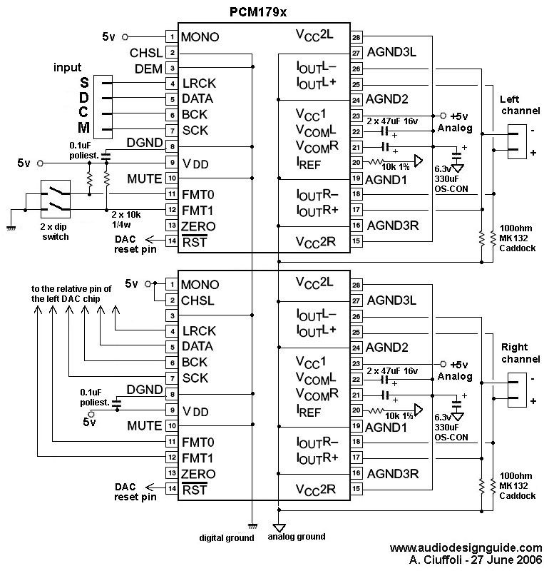
These DAC chips does not have a current output so in mono configuration (differential) is necessary to add resistors on analog output to merge these.
In the schematic there are 2k 1% but I have used a parallel of 2 x 4k 1% to reduce their inductance.
Obviously these resistances increase the DAC output impedance so with load less than 10k the output voltage will decrease.
In the complete headphone amp. with LL7903 and BUF634 the DACT 50K create an high load but the output level is still good to drive an headphone.
In any case in the future I will try to reduce these 2k output resistances.
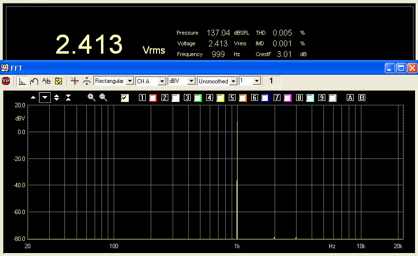
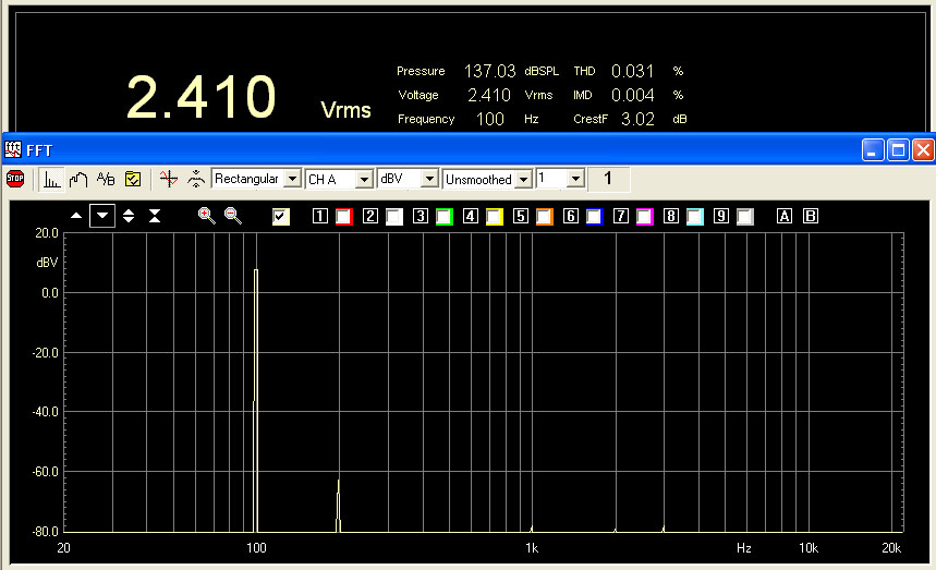
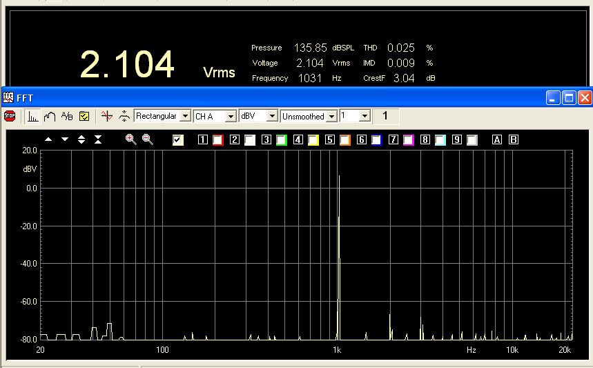
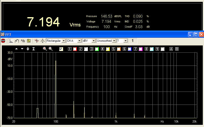
Follows the measurement on this DAC board outputs.

I have implemented a passive I/V converter with 4 x 100ohm Caddock resistors.
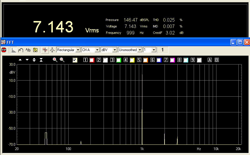
Follows the measurement on DAC board outputs.

AD1955 in MONO
|
|
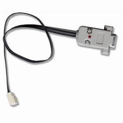
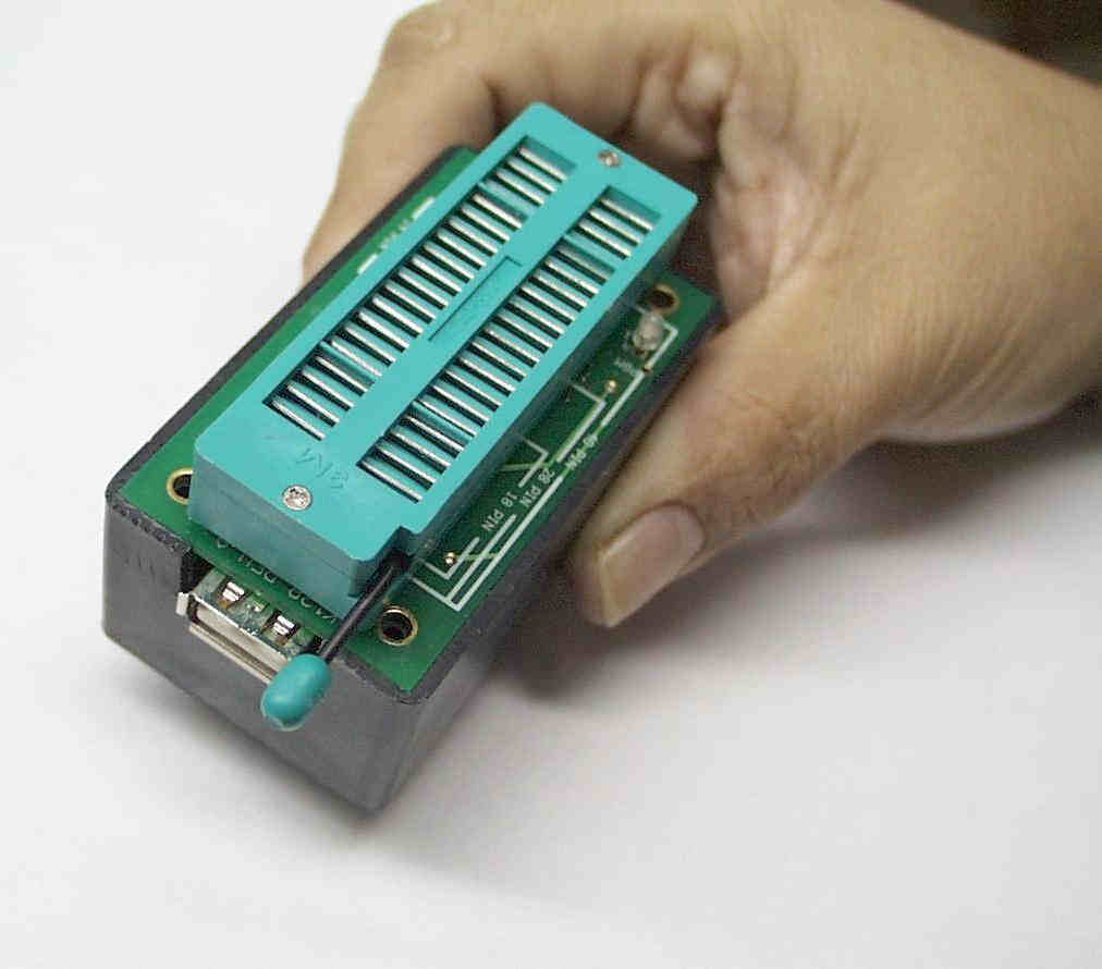
As microcontroller I have used a
Microchip Enhanced Flash type
that can be to programmed with a very simple method called:
In-Circuit Serial Programming™ (ICSP™). Using this method is possible program the chip directly on the final board adding only little a connector and a switch to select the 2 modes: run or program. To connect a PC to the ICSP port on the board it is necessary only a Serial Port Programmer available for few money from Spark Fun. I have got some problems with Serial Port Programmer if used with laptop computers so in these case use an USB programmer with ZIF socket like the DIY K128 by kitsrus.com. I have develop the program in C language and I have compile it with a freeware version of the C compiler get from HI-TEC Software in the Download / Demos & free software selection PIC-LITE (Windows), also a Linux version is available. I have used the model 16F876A but also a 12F629 could be good for this porpose. The 16F876A is not supported with the freeware version of the HI-TEC C compiler but can be select the 16F877A without problem because these 2 PIC have the same memory address. The
command line to compile the source code is: With the Serial Port Programmer as programmer I have used the freeware Winpic software selecting the "JDM" as interface. |


 |
About passive components types, I don't leave many choices:
Caddock resistances on cathode, ELNA Cerafine or Sanyo OS-CON
capacitors.
A valid alternative to the expensive Caddock is to use a
parallel of two normal 1% metallic oxide resistor with inverted
phase to compensate some of their inductance. |
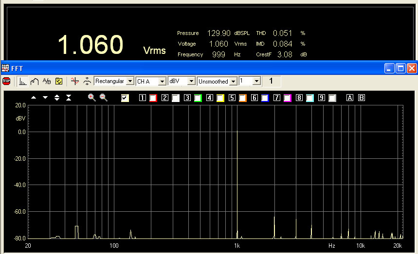
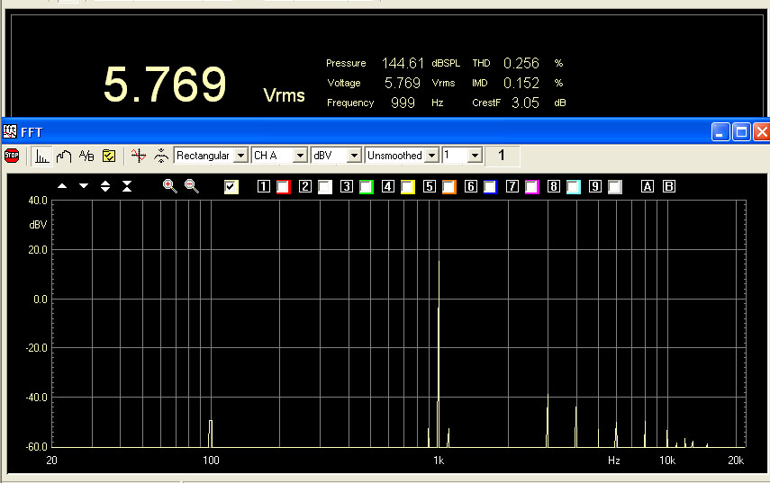
Follows the measurement on DAC board outputs.
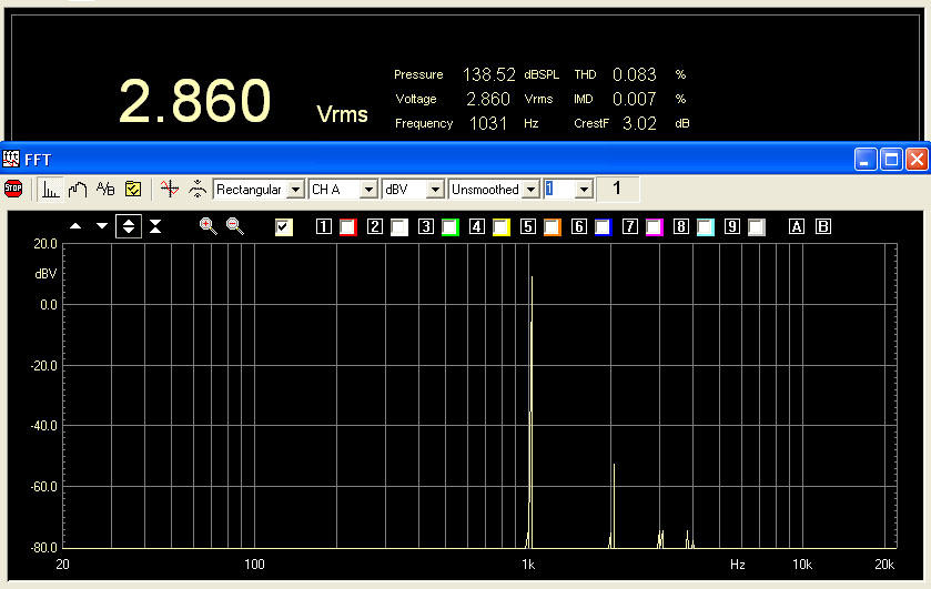
In this case the max load to apply should be 100Kohm (the DAC will see 100k / (8 * 8) = 1500 ohm) but this high output level can be used to drive a power buffer.
It is possible with a trimmer compensate the operational amplifier dc offset to skip the RC cell on transformer's primary.
Follows some measurements with BUF634 or with a 2sk216 connected on transformer's secondary to reduce output impedance and load headphones.
The dynamic range could be increase using for the BUF634 a power supply near to +-18V.
MEASUREMENT RESULTS
Follows a new comparing table for these DAC chips about measurement
results.
| Feature |
Crystal |
Wolfson |
Burr-Brown |
Burr-Brown |
Analog Devices |
Burr-Brown |
| DAC chip |
WM8740 mono | PCM1798 mono | PCM1794 mono | PCM1794 mono active I/V | ||
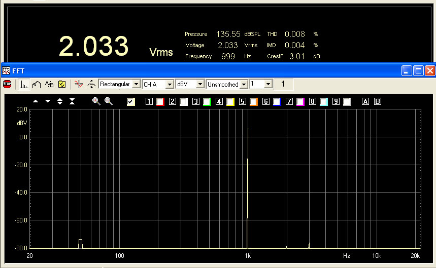
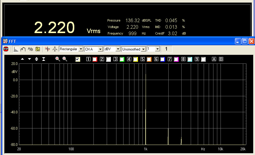
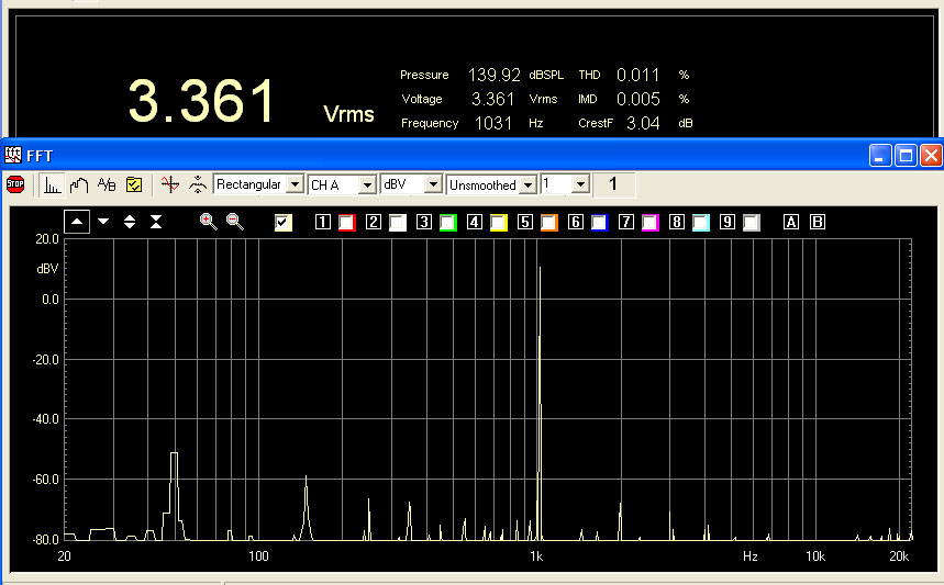
| Single DAC output [Vrms] |
1.132 | 0.9 | 0.244 | 0.480 | 2.86 |
4.074 |
| Single DAC output THD @ 0dB [%] |
0.006 | 0.045 | 0.029 | 0.038 | 0.083 | 0.074 |
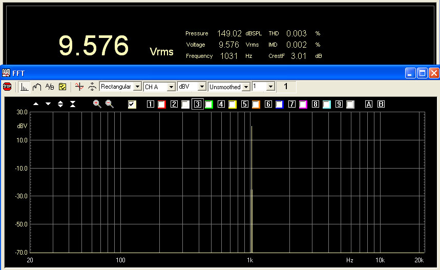
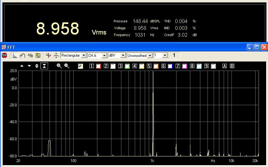
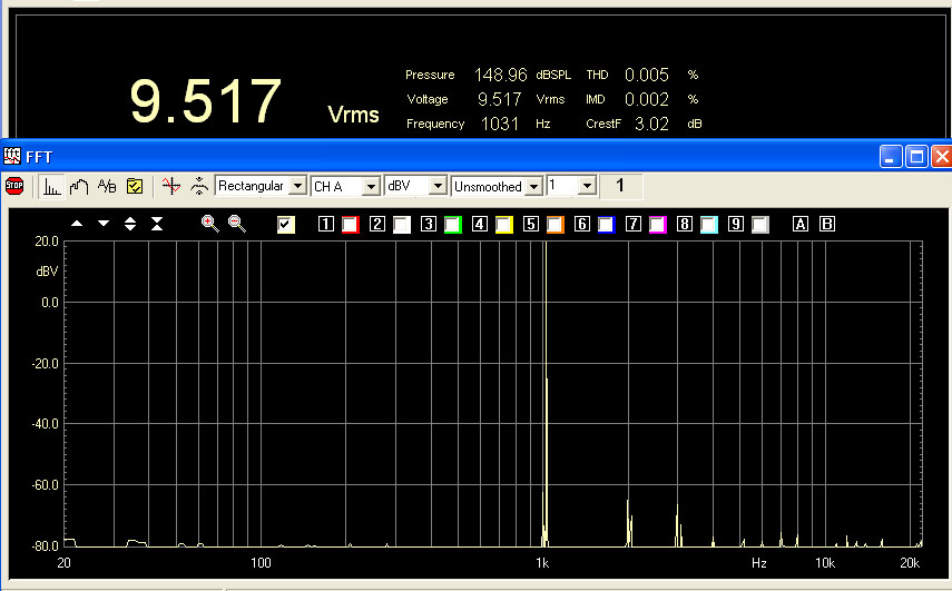
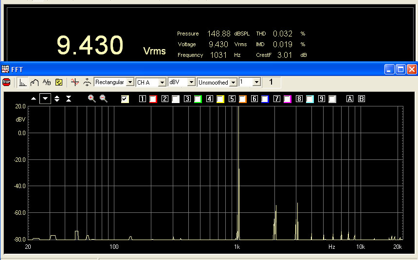
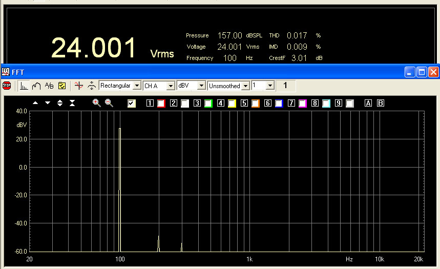
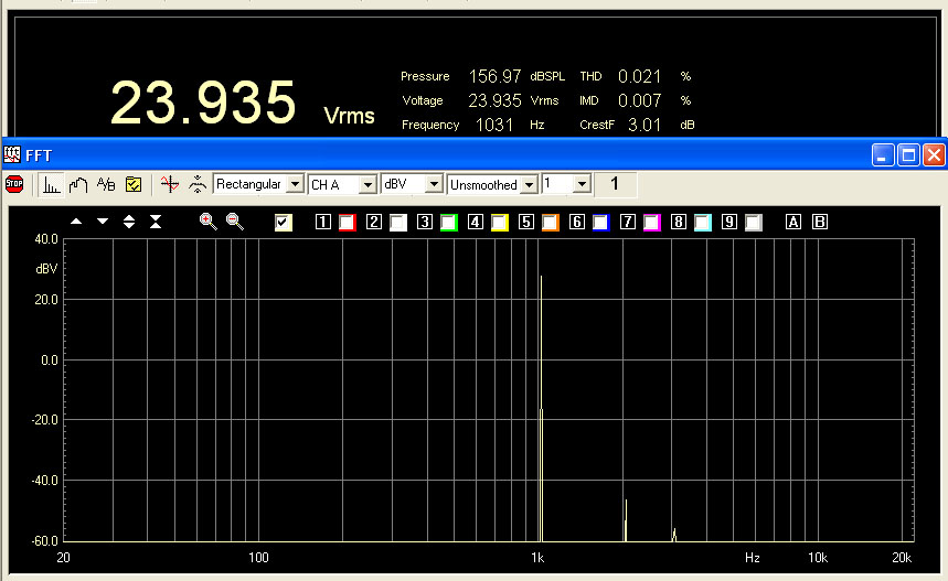
| DAC board + LL7903 connection n. 3 [Vrms] | 9.57 | 4.4 | 4 | 24 | 32 | |
| DAC board + LL7903 connection n. 3 [%] | 0.003 | 0.009 | 0.008 | 0.021 | 0.059 | |
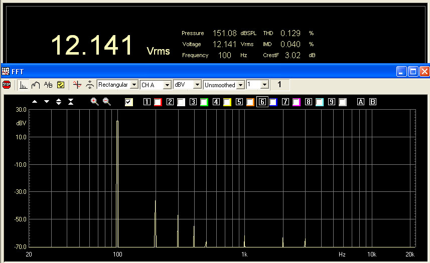
| DAC board + LL7903 connection n. 2 [Vrms] | 1 | 2.1 | 12.1 | |||
| DAC board + LL7903 connection n. 2 [%] | 0.050 | 0.025 | 0.021 | |||
| DAC board + LL7903 connection n. 1 [Vrms] | 2.4 | - | - | 8.32 | ||
| DAC board + LL7903 connection n. 1 [%] | 0.005 | - | - | 0.066 |
In this table is visible the high distortion reduction after the differential output stage for Analog Device, Wolfson and Burr-Brown that means a very little difference of DAC stage in the same chip.
In fact for differential output DAC is not important the distortion level before the differential stage (Single DAC output).
SONIC RESULT
TEST1
TEST2
One my
friend (Max) (different from the previous test) with a lot of experience on music reproduction
were
present at the test.
Grades are on a 1-10 scale, where 10 is the absolute best
and the test duration
has been 3 hours.
The DAC
boards have driven a
Lundahl LL7903
connected in 1+1:2
followed by a DACT stepper attenuator.
In all the 4 boards all the normal capacitors has been
replaced with
Sanyo OS-CON.
The
PCM1798
now use an
active I/V converter made using an OP275 (see
photo).
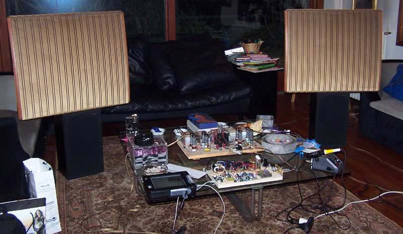
The amplifier was a prototype of my
EL34 PSE with Lundahl transformers, with Jensen copper
film interstage capacitors, Svetlana matched quartet output
tubes and Jan Philips (12AX7 - 5814) drivers. One of my best
amplifiers.
The Loudspeakers cables was the Monitor Cobra and as
loudspeakers QUAD ESL 57 from 1972 of one of my friends.
TEST3

One my
friend (Mon) (different from both previous tests) with a lot of experience on music reproduction
were
present at the test.
Grades are on a 1-10 scale, where 10 is the absolute best
and the test duration
has been 3 hours.
The DAC boards have driven a
Lundahl LL7903
connected in 1+1:2
followed by a DACT stepper attenuator.
In all the 4 boards all the normal capacitors has been
replaced with
Sanyo OS-CON.
The
PCM1798
now use an
active I/V converter made using an OP275 (see
photo).
Tthe
CS4397
board use 2 x 1Kohm resistors on CMOUT pin like the CDB4397
board and this increase detail.
The amplifier
was a LM3875 Dual Mono Premium Kit by
www.audiosector.com
with all Caddock resistances and components close to the
Gaincard amplifier by
http://www.sakurasystems.com with a price about $,1500
and review on
http://www.enjoythemusic.com/Magazine/equipment/999/47review.htm.
The Interconnect cable was the superlative
Tao
Analogue Interconnect by Q-Audio.
The loudspeakers was my AV system using SEAS COAX driver and
project by Punto Musica.
Some comments to
the result as been given in this case.
| Feature |
Crystal |
Wolfson |
Burr-Brown |
Analog Devices |
| DAC chip |
WM8740 mono | PCM1798 mono | ||
| test 1 | 5 | 8.5 | 4.5 | 9.5 |
| test 2 | 6 | 7 | 4 | 9 |
| test 3 |
6 bit too smooth |
8 fantastic |
7 too banal |
5 too analytic |